

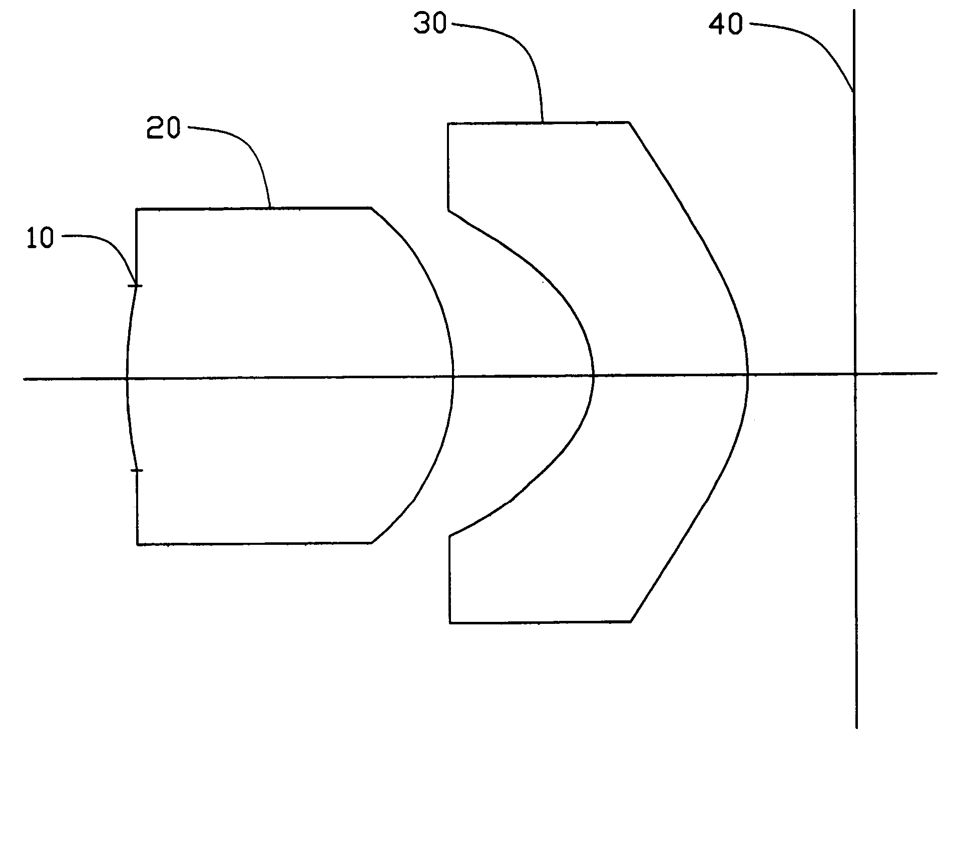
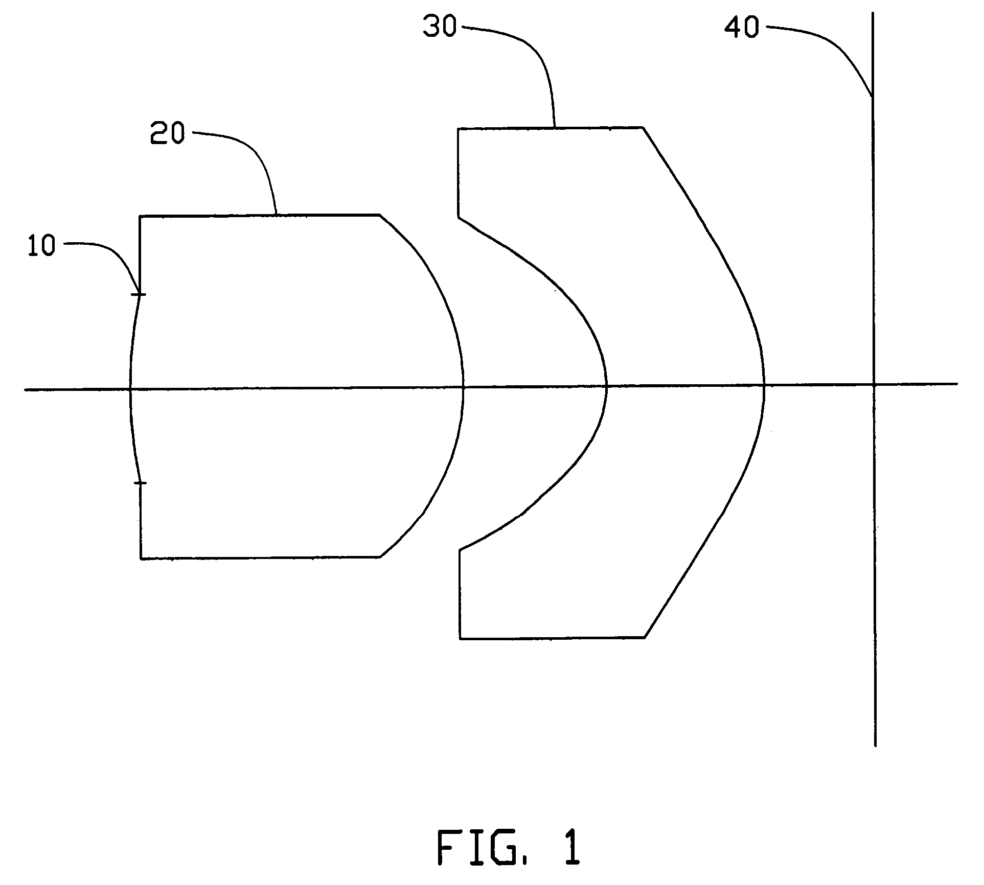
Image pick-up lens system
a technology of image pick-up and lens system, which is applied in the field of image pick-up lens system, can solve the problems of difficult to achieve excellent optical performance, difficult to compact the lens system, and the general use of a single lens system in a low-resolution image pick-up device such as a cmos, etc., and achieves the effect of short total length
- Summary
- Abstract
- Description
- Claims
- Application Information
AI Technical Summary
Benefits of technology
Problems solved by technology
Method used
Image

Examples
example 1
[0055]Tables 1 and 2 show lens data of Example 1.
[0056]
TABLE 1f = 3.21 mm T = 4.00 mm FNo = 2.83 ω = 35°Surface No.R (mm)D (mm)NdνkStop 10infinite−0.0801st surface1.9086851.9497671.49257.40.39693742nd surface−1.3860190.84108080.43224713rd surface−0.63138170.92961561.58529.9−0.67372034th surface−1.1404750.2679967−0.9677394
[0057]
TABLE 2Surface No.1st surface2nd surface3rd surface4th surfaceAsphericalA2 = 0A2 = 0A2 = 0A2 = 0coefficientA4 = −0.037981674A4 = 0.040516016A4 = −0.04769116A4 = −0.0026459285A6 = −0.11117147A6 = −0.0040262084A6 = 0.05474841A6 = 0.0088382976A8 = 0.25717755A8 = −0.0022363842A8 = 0.018494473A8 = 0.0026971968A10 = −0.44540332A10 = 0.0040769403A10 = −0.0063129926A10 = 0.00071976951A12 = 0.1964647A12 = −0.0011660921A12 = −0.002450423A12 = −0.00036281554A14 = 0A14 = 0A14 = 0A14 = 0A16 = 0A16 = 0A16 = 0A16 = 0
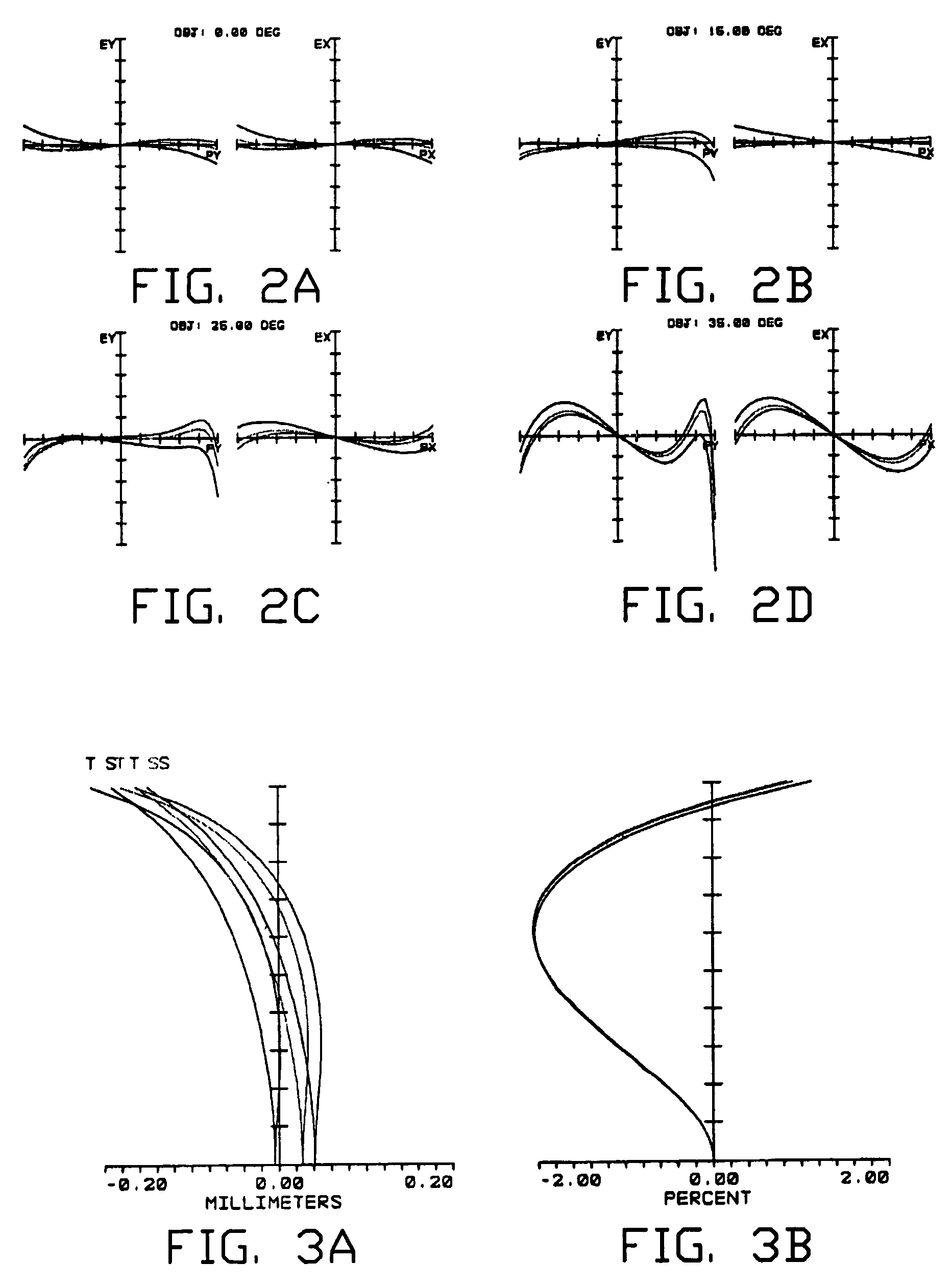
[0058]FIGS. 2-5 are graphs of aberrations (transverse ray fan plots, field curvature / distortion, longitudinal spherical aberration, and lateral chromatic aberrat...
example 2
[0059]Lens data of Example 2 are shown in tables 3 and 4.
[0060]
TABLE 3f = 3.19 mm T = 3.99 mm FNo = 2.80 ω = 35°Surface No.R (mm)D (mm)NdνkStop 10infinite−0.0801st surface1.8957221.9340081.49257.4−1.0313952nd surface−1.3761860.83481530.4410943rd surface−0.62426780.91180451.58529.9−0.6737484th surface−1.1262450.3122−0.9667288
[0061]
TABLE 4Surface No.1st surface2nd surface3rd surface4th surfaceAsphericalA2 = 0A2 = 0A2 = 0A2 = 0coefficientA4 = −0.0086994569A4 = 0.041163675A4 = −0.048693006A4 = −0.0027907875A6 = −0.1161784A6 = −0.0042075403A6 = 0.057214163A6 = 0.0092363559A8 = 0.27353815A8 = −0.002378654A8 = 0.019671017A8 = 0.0028687816A10 = −0.48215993A10 = 0.0044133871A10 = −0.0068339682A10 = 0.00077916802A12 = 0.21645868A12 = −0.0012847639A12 = −0.0026997998A12 = −0.00039973886A14 = 0A14 = 0A14 = 0A14 = 0A16 = 0A16 = 0A16 = 0A16 = 0
[0062]FIGS. 6-9 are graphs of aberrations (transverse ray fan plots, field curvature / distortion, longitudinal spherical aberration, and lateral chromatic a...
example 3
[0063]Lens data of Example 3 are shown in tables 5 and 6. In the lens data shown below, E shows powers of 10; that is, for example, 2.5E-0.3 means 2.5×10⁻³.
[0064]
TABLE 5f = 3.21 mm T = 4.05 mm FNo = 2.83 ω = 35°Surface No.R (mm)D (mm)NdνkStop 10infinite−0.079801st surface1.9375761.9511231.49257.4−1.0263662nd surface−1.3956950.8422030.36498433rd surface−0.63674270.91987351.58529.9−0.67821414th surface−1.1115850.3119658−4.560295
[0065]
TABLE 6Surface No.1st surface2nd surface3rd surface4th surfaceAsphericalA2 = 0A2 = 0A2 = 0A2 = 0coefficientA4 = −0.0090154464A4 = 0.047546265A4 = −0.067457258A4 = −0.17525752A6 = −0.027257396A6 = −0.067428703A6 = 0.048702325A6 = 0.053841628A8 = −0.31450985A8 = 0.088613357A8 = −0.0016956663A8 = 0.0007158852A10 = 0.60707428A10 = −0.04786747A10 = −8.414046E−005A10 = −0.001238689A12 = 0A12 = 0A12 = 0A12 = 0A14 = 0A14 = 0A14 = 0A14 = 0A16 = 0A16 = 0A16 = 0A16 = 0
[0066]FIGS. 10-13 are graphs of aberrations (transverse ray fan plots, field curvature / distortion, ...
PUM
 Abstract
Description
Claims
Application Information