Cement telegraph pole rapid conveying and mounting equipment

A technology for cement poles and fast transportation, which is applied in the direction of building types, buildings, towers, etc., and can solve the problems of low transportation efficiency, time-consuming and labor-intensive manual erection, etc.

Inactive Publication Date: 2017-10-10
南昌叁润科技有限公司
View PDF8 Cites 9 Cited by
  • Summary
  • Abstract
  • Description
  • Claims
  • Application Information

AI Technical Summary

Problems solved by technology

[0006] In order to overcome the shortcomings of the current transportation and installation of cement utility poles, which require multiple times of transportation of cement utility poles, the efficiency of the cement utility poles is low, and the installation process is time-consuming and labor-intensive for manual erection, the technical problem to be solved by the invention is to provide It is a kind of fast transportation and installation equipment for cement utility poles that need to be transported multiple times for cement utility poles, which has high efficiency and saves time and effort during installation

Method used


Image

  • Cement telegraph pole rapid conveying and mounting equipment
  • Cement telegraph pole rapid conveying and mounting equipment
  • Cement telegraph pole rapid conveying and mounting equipment

Examples


Embodiment 1

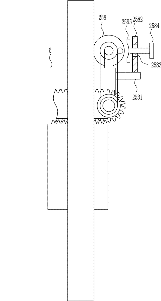
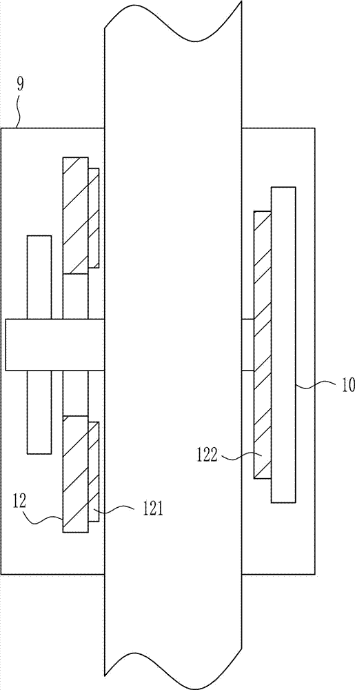
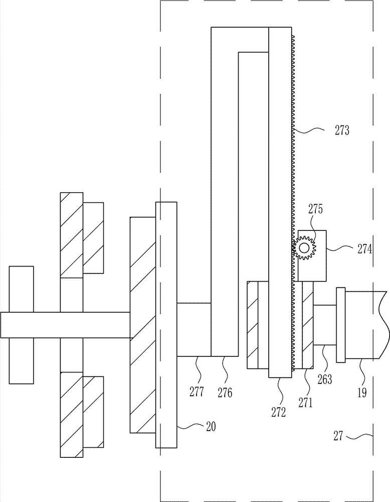
[0038] A kind of equipment for fast transportation and installation of cement utility poles, such as Figure 1-8 As shown, it includes a mounting plate 1, a first support seat 2, a wheel shaft 3, a tire 4, a support plate 5, a fixed plate 6, a second support seat 7, a first guide rail 8, a first guide sleeve 9, and a first splint 10 , the first screw rod 11, the second splint 12, the first nut 14, the first connecting block 15, the placement block 16, the bearing seat 17, the rotating ring 18, the connecting rod 19, the third splint 20, the second screw rod 21, the fourth The splint 22 and the second nut 24, the first support seat 2 is installed on the left and right sides and the front and rear sides of the lower side of the mounting plate 1 by welding, the lower side of the first support seat 2 is rotatably connected to the wheel shaft 3, and the wheel shaft 3 is connected to There are tires 4, a support plate 5 is installed on the right side and rear of the mounting plate 1...

Embodiment 2

[0040] A kind of equipment for fast transportation and installation of cement utility poles, such as Figure 1-8 As shown, it includes a mounting plate 1, a first support seat 2, a wheel shaft 3, a tire 4, a support plate 5, a fixed plate 6, a second support seat 7, a first guide rail 8, a first guide sleeve 9, and a first splint 10 , the first screw rod 11, the second splint 12, the first nut 14, the first connecting block 15, the placement block 16, the bearing seat 17, the rotating ring 18, the connecting rod 19, the third splint 20, the second screw rod 21, the fourth The splint 22 and the second nut 24, the first support seat 2 is installed on the left and right sides and the front and rear sides of the lower side of the mounting plate 1 by welding, the lower side of the first support seat 2 is rotatably connected to the wheel shaft 3, and the wheel shaft 3 is connected to There are tires 4, a support plate 5 is installed on the right side and rear of the mounting plate 1...

Embodiment 3

[0043] A kind of equipment for fast transportation and installation of cement utility poles, such as Figure 1-8As shown, it includes a mounting plate 1, a first support seat 2, a wheel shaft 3, a tire 4, a support plate 5, a fixed plate 6, a second support seat 7, a first guide rail 8, a first guide sleeve 9, and a first splint 10 , the first screw rod 11, the second splint 12, the first nut 14, the first connecting block 15, the placement block 16, the bearing seat 17, the rotating ring 18, the connecting rod 19, the third splint 20, the second screw rod 21, the fourth The splint 22 and the second nut 24, the first support seat 2 is installed on the left and right sides and the front and rear sides of the lower side of the mounting plate 1 by welding, the lower side of the first support seat 2 is rotatably connected to the wheel shaft 3, and the wheel shaft 3 is connected to There are tires 4, a support plate 5 is installed on the right side and rear of the mounting plate 1 ...


PUM


Abstract

The invention relates to telegraph pole mounting equipment, in particular to cement telegraph pole rapid conveying and mounting equipment. According to the cement telegraph pole rapid conveying and mounting equipment, cement telegraph poles do not need to be conveyed many times, efficiency is high, and vertical standing of the equipment saves the time and labor in the mounting process. The cement telegraph pole rapid conveying and mounting equipment comprises a mounting plate, first supporting seats, wheel shafts, tires, a supporting plate, a fixing plate, a second supporting seat, a first guiding rail, first guiding sleeves, first clamping plates, first screws and the like. The first supporting seats are mounted on the left side, right side, front side and rear side of the lower side of the mounting plate in a welded mode, the wheel shafts are connected to the lower sides of the first supporting seats in a rotating mode, and the tires are connected to the wheel shafts. According to the cement telegraph pole rapid conveying and mounting equipment, the effects that the cement telegraph poles do not need to be conveyed many times, the efficiency is high, and vertical standing of the equipment saves the time and labor in the mounting process are achieved.

Description

technical field [0001] The invention relates to a utility pole installation device, in particular to a cement utility pole fast transportation and installation facility. Background technique [0002] Telephone poles, as the name suggests, are poles for wires. Appearing in various villages-fields-roads-streets, it was one of the important infrastructures in early China. All kinds of electric poles in the early days started from wooden poles, even including high-voltage electric poles whose voltage level was not too high. Later, due to the development of steel and reinforced concrete, and technical requirements, these two materials replaced most of the wooden poles, and the applicable wood was gradually scarce, and it was basically difficult to see wooden poles in the city. However, in some less developed places, wooden poles are still used to erect telephone lines, because wooden poles are light in weight and easy to erect, and the load-bearing and tensile force of telephon...

Claims


Application Information

Patent Timeline
Patent Type & Authority Applications(China)
IPC IPC(8): E04H12/34
CPCE04H12/34
Inventor 卢磊江思明余强
Owner 南昌叁润科技有限公司
Why Eureka
Try Eureka