
Electric valve and assembly method thereof

A technology of electric valves and spools, applied in the direction of valve devices, valve operation/release devices, valve lifts, etc., to achieve the effect of suppressing size deviation

Active Publication Date: 2020-05-01
FUJIKOKI MFG CO LTD
View PDF9 Cites 0 Cited by
  • Summary
  • Abstract
  • Description
  • Claims
  • Application Information

AI Technical Summary

Problems solved by technology

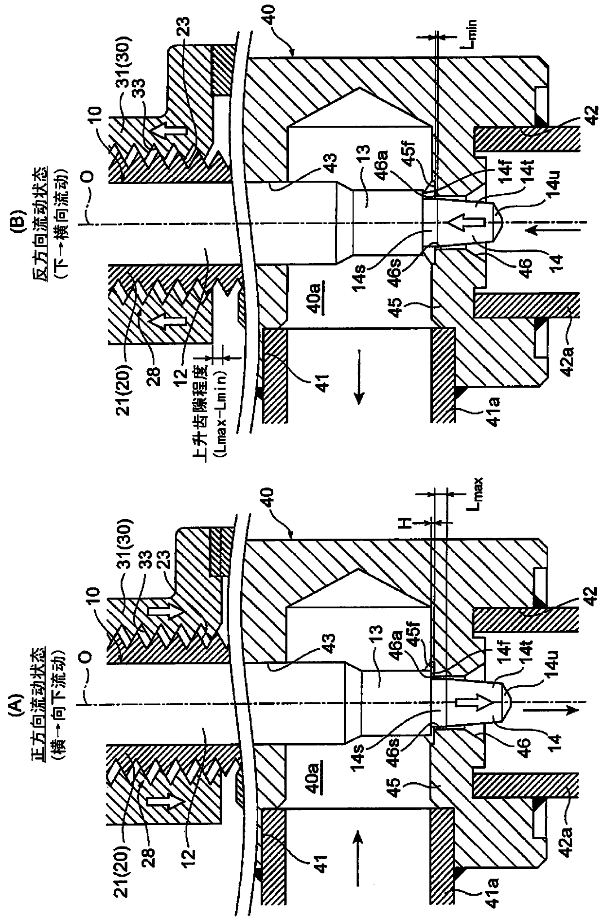
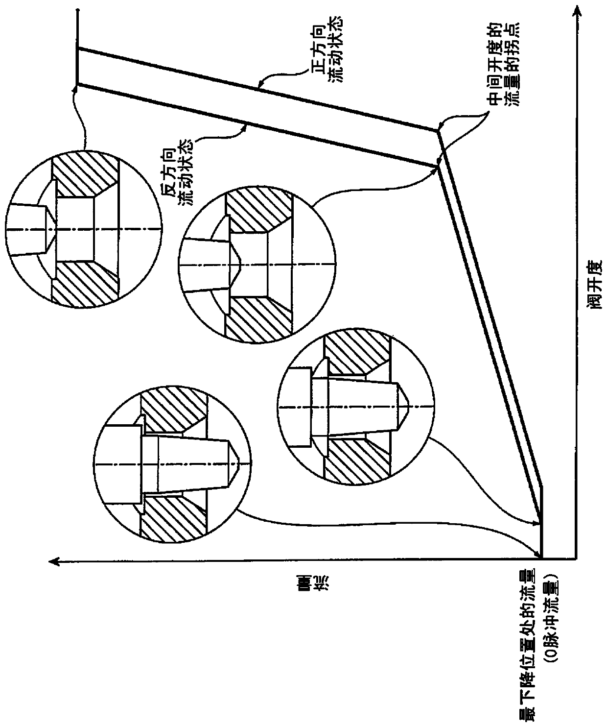
Therefore, there is a problem that the spool moves up and down relative to the valve seat due to the change in the flow direction of the fluid as described above. When the number is the position of 0 pulses), the passing flow rate (also called 0 pulse flow rate) of the fluid flowing through the orifice of the valve port changes before and after the flow direction of the fluid changes (refer to Figure 8 )

Method used


Image

  • Electric valve and assembly method thereof
  • Electric valve and assembly method thereof
  • Electric valve and assembly method thereof

Examples


Embodiment Construction

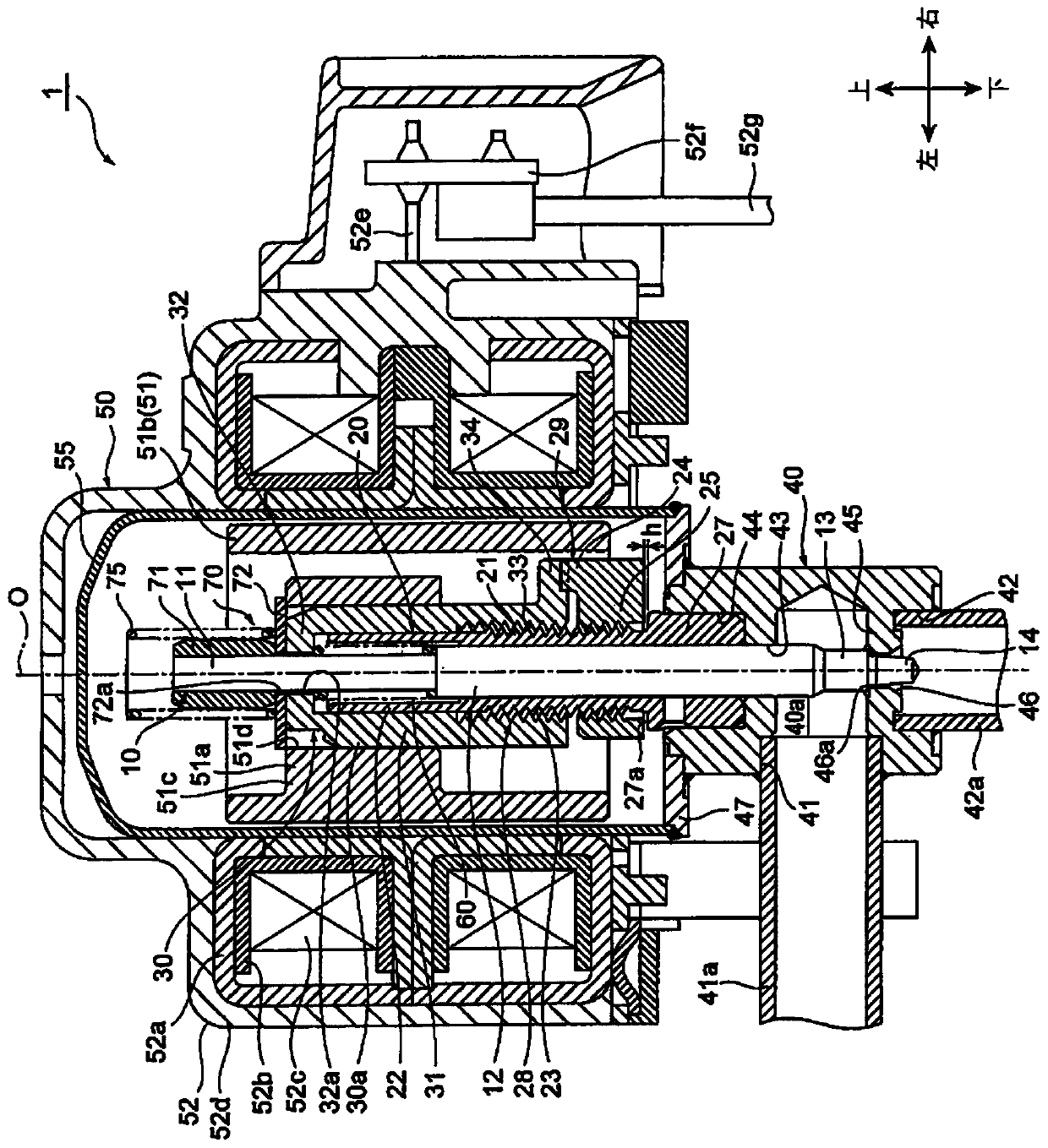
[0064] Hereinafter, specific embodiments of the electric valve and its assembly method according to the present invention will be described with reference to the drawings. In addition, in order to facilitate understanding of the invention and in consideration of drawing convenience, in each figure, gaps formed between components and separation distances between components may be exaggeratedly drawn. In addition, in this specification, it indicates positions such as up and down, left and right, and the description of directions is based on figure 1 The direction arrows in the middle indicate the reference, not the position and direction in the actual use state.

[0065] Also, in this specification, the direction from the first conduit to the second conduit via the valve chamber and the valve port orifice is taken as the "positive direction", and the direction from the second conduit to the first conduit via the valve port orifice and the valve chamber is taken as the "positive...


PUM


Abstract

Provided is an electric valve and an assembly method thereof capable of suppressing a change in the flow rate accompanying a change in the flow direction of a fluid (refrigerant) when the valve element is at the most descended position. When the valve core (14) is at the most descending position, at least a part of the straight part (14s) on the side of the valve core (14) and at least a part of the straight part (46s) on the side of the valve seat part (46a) overlap in the lifting direction.

Description

technical field [0001] The present invention relates to an electric valve installed in the refrigeration cycle of an air conditioner, refrigerator, etc. A non-closing electric valve in which a gap of a predetermined size is formed between valve seats and an assembly method thereof. Background technique [0002] As such an electric valve, for example, there is known a structure comprising: a valve shaft; a guide rod having a cylindrical portion inserted into the valve shaft; held and fixed to the lower end of the valve shaft and inserted into the The cylindrical valve holder of the guide rod; the valve core, which is inserted into the valve holder in a state capable of relative movement and relative rotation relative to the valve shaft in the axial direction, and is mounted on the valve by compression. The coil spring between the valve core and the valve shaft is forced downward, and is locked by the valve retainer; the valve main body has a valve seat that is in contact wit...

Claims


Application Information

Patent Timeline
Patent Type & Authority Patents(China)
IPC IPC(8): F16K31/04F16K1/36F16K1/42F16K1/32
CPCF16K1/32F16K1/36F16K1/42F16K31/041F16K1/04F16K27/02Y02B30/70F16K31/047F25B41/20F16K31/50F16K31/043F16K27/029
Inventor 矢泽将志吉田龙也
Owner FUJIKOKI MFG CO LTD
Learn More