
Crawler unit

A walking mechanism and crawler technology, which is applied in the field of machinery, can solve the problems of not meeting the requirements of climbing and walking, derailment and overturning of the crawler belt, and low grip of the crawler belt, so as to prevent the risk of derailment and tipping of the crawler belt, and reduce vibration and impact , The effect of increased track grip

Active Publication Date: 2017-10-13
SHANGHAI GRAMAN INT FIRE EQUIP
View PDF7 Cites 3 Cited by
  • Summary
  • Abstract
  • Description
  • Claims
  • Application Information

AI Technical Summary

Problems solved by technology

This kind of crawler walking system makes the driving wheel located at a relatively high position of the walking system, although it can avoid the driving wheel from being hit by external obstacles during walking, so that when the walking system encounters an obstacle, the swing and suspension of the tension wheel The damping effect of the shock absorbing device can improve the obstacle-surpassing ability of the whole machine, but when climbing a slope, there are small track grip, reduced traction, large climbing resistance, poor stability, and easy to cause the risk of track derailment and tipping, which cannot meet the needs of tractors. , bulldozers, excavators, robots and other crawler machinery climbing and walking requirements

Method used


Image

  • Crawler unit
  • Crawler unit
  • Crawler unit

Examples


Embodiment

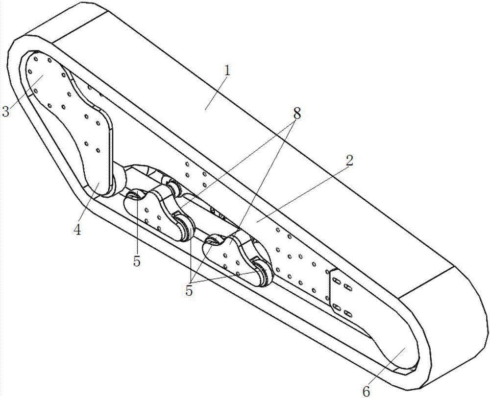
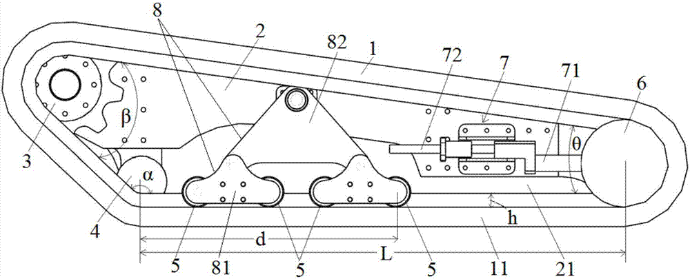
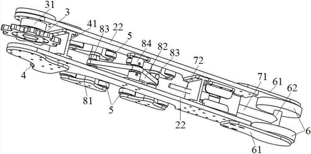
[0026] combine figure 1 and figure 2 Shown: a crawler running mechanism provided in this embodiment, including a crawler 1, a crawler beam 2, a driving wheel 3, a fixed supporting wheel 4, a floating supporting wheel 5 and a tensioning wheel 6, the driving wheel 3 Located at the front end of the track beam 2, the tension wheel 6 is located at the rear end of the track beam 2, and the fixed track roller 4 and the floating track roller 5 are located between the driving wheel 3 and the tension wheel 6, and are fixed The fixed roller 4 is located in front of the floating roller 5, and the fixed roller 4 is on the same ground plane as the floating roller 5 and the tension roller 6. The distance d between the centers of gravity of the floating rollers 5 accounts for 40% to 70% (preferably 50% to 60%) of the length L of the ground track 11, so that the overall center of gravity can move forward to the fixed rollers when climbing. 4), the track 1 surrounds the driving wheel 3, the ...


PUM


Abstract

The invention discloses a crawler unit. The crawler unit comprises a crawler, a crawler beam, a driving wheel, a fixed type supporting wheel, a floating type supporting wheel and a tensioning wheel, wherein the driving wheel is positioned at the front end of the crawler beam; the tensioning wheel is positioned at the rear end of the crawler beam; the crawler beam comprises two side beams; the fixed type supporting wheel and the floating type supporting wheel are positioned between the driving wheel and the tensioning wheel; the fixed type supporting wheel is positioned in front of the floating type supporting wheel; the fixed type supporting wheel, the floating type supporting wheel and the tensioning wheel are positioned on the same grounded plane; the distance from the center of gravity of the fixed type supporting wheel to the center of gravity of the hindmost floating type supporting wheel accounts for 40-70% of the length of the crawler, the crawler surrounds the driving wheel, the tensioning wheel, the floating type supporting wheel and the fixed type supporting wheel to form an obtuse triangle structure with an upward obtuse angle; the vertex of the obtuse angle is the fixed type supporting wheel; and the crawler beam which is arranged between the rear of the floating type supporting wheel and the front of the tensioning wheel is suspended on the grounded crawler.

Description

technical field [0001] The invention relates to a crawler belt traveling mechanism, which belongs to the technical field of machinery. Background technique [0002] The crawler type walking system is the most widely used walking system after the tire type in construction machinery. It has been widely used in various construction machinery, forming various crawler type construction machinery. Common tracked machinery includes: tractors, bulldozers, excavators, harvesters, robots, etc. At present, when the crawler walking system crosses obstacles, it is only guided by the supporting weight of the middle roller, which causes the front or rear of the vehicle to warp instantly when walking, and is prone to derailment of the track, which brings great harm to the vehicle or the operator. The impact of the impact will not only affect the efficiency of the machine, but also shorten the service life of the track and increase the cost of maintenance and use. [0003] Chinese utility ...

Claims


Application Information

Patent Timeline
Patent Type & Authority Applications(China)
IPC IPC(8): B62D55/08B62D55/10B62D55/15B62D55/14B62D55/30
CPCB62D55/08B62D55/10B62D55/14B62D55/15B62D55/30
Inventor 袁绪猛花冰谢奕波陈开纬严俊春林佳李建谢毅王军
Owner SHANGHAI GRAMAN INT FIRE EQUIP
Learn More