
A three-in-one energy utilization device of turbine, condenser and circulating water pump

A technology for circulating water pumps and condensers, which is applied in steam engine installations, steam/steam condensers, steam recovery, etc., and can solve the problem of low working torque of Tesla disc turbines, which cannot adapt to the high flow rate and low speed of steam exhaust units Needs, blade propulsion is small and other issues, to achieve low cost, improve energy conversion efficiency, improve the effect of working torque

Active Publication Date: 2019-03-05
HUAZHONG UNIV OF SCI & TECH
View PDF5 Cites 0 Cited by
  • Summary
  • Abstract
  • Description
  • Claims
  • Application Information

AI Technical Summary

Problems solved by technology

Since the working parts of the Tesla disk turbine are disks, the fluid between different disks can fully exchange heat. Therefore, although the Tesla disk turbine has the necessary conditions for working as a condenser to achieve energy conversion, but There are still some problems: (1) Although the Tesla disk turbine has the above advantages, there is no precedent for using the Tesla disk turbine in the condenser to realize energy utilization. (2) The working torque of the traditional Tesla disk turbine Small, it can only run at high speed and low torque, and cannot meet the needs of high flow and low speed steam of the exhaust steam unit. (3) The blades of the traditional Tesla disk turbine are disc-shaped, and the working fluid is on the blades. less driving force

Method used


Image

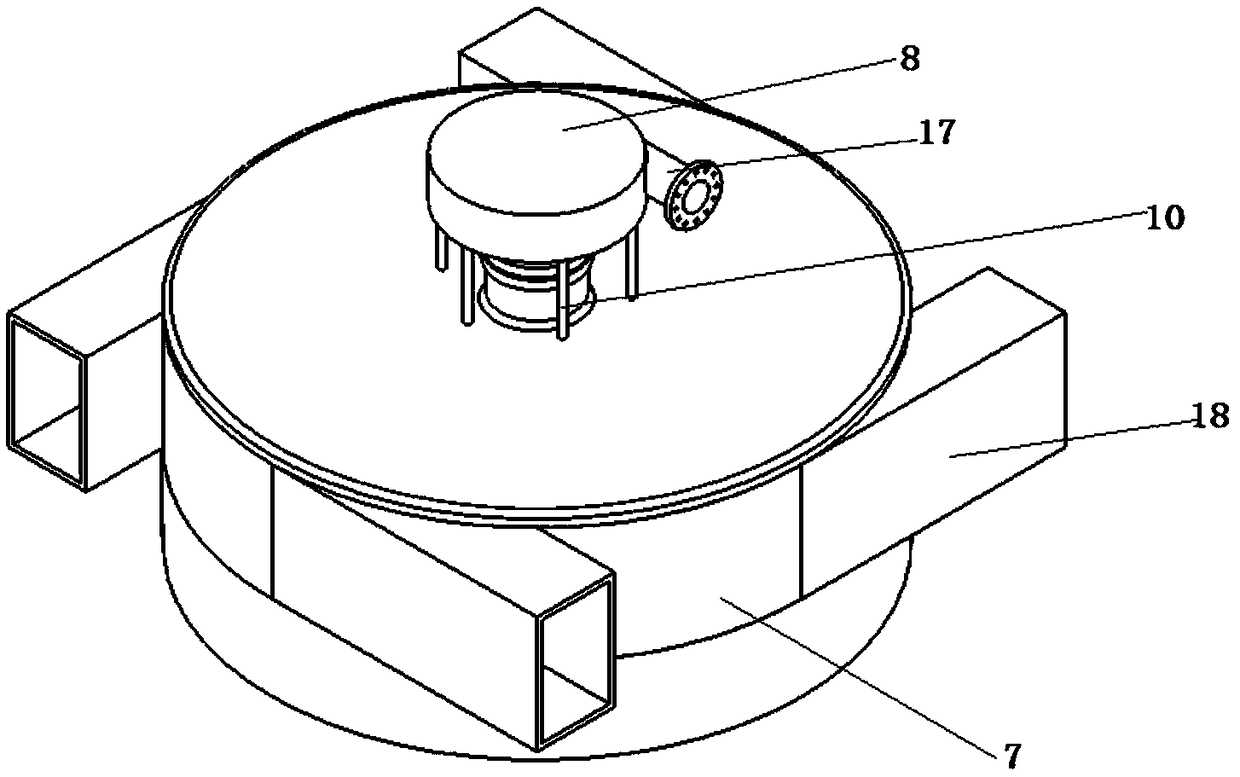
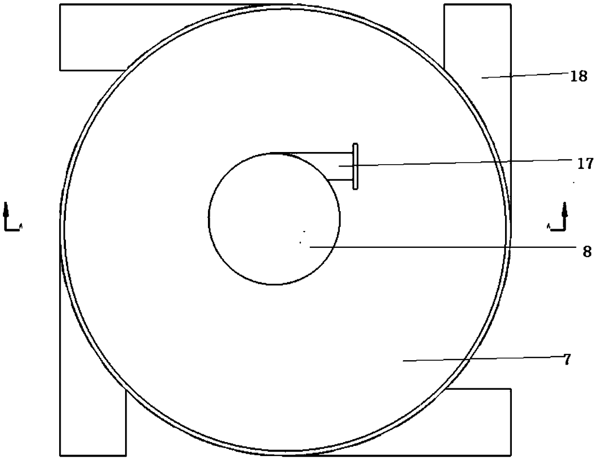
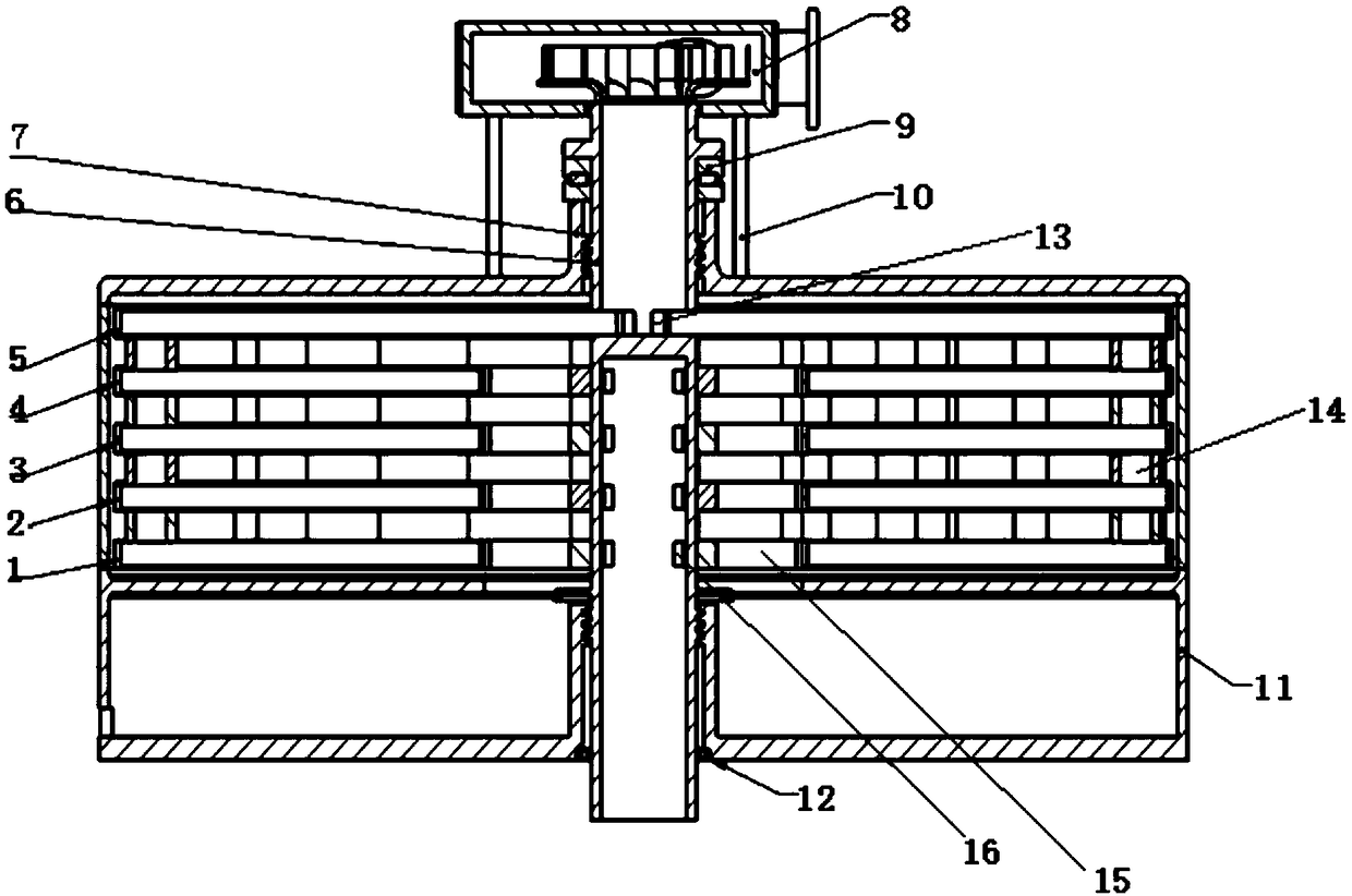
  • A three-in-one energy utilization device of turbine, condenser and circulating water pump
  • A three-in-one energy utilization device of turbine, condenser and circulating water pump
  • A three-in-one energy utilization device of turbine, condenser and circulating water pump

Examples


Embodiment Construction

[0036] In order to make the object, technical solution and advantages of the present invention clearer, the present invention will be further described in detail below in conjunction with the accompanying drawings and embodiments. It should be understood that the specific embodiments described here are only used to explain the present invention, not to limit the present invention. In addition, the technical features involved in the various embodiments of the present invention described below can be combined with each other as long as they do not constitute a conflict with each other.

[0037] The present invention provides a three-in-one energy utilization device of a disc turbine, a condenser and a circulating water pump. The present invention will be further described below in conjunction with the accompanying drawings and implementation examples.

[0038] As shown in Fig. 1 (a)-(c), the energy utilization device of a kind of steam turbine exhaust driven disc turbine, conden...


PUM


Abstract

The invention belongs to the field of energy saving and emission reducing equipment, and in particular, relates to a turbine, condenser and circulating water pump three-in-one energy utilization device. The device comprises a rotating shaft, a circulating water pump arranged at the top of the rotating shaft, a condenser sleeved at the upper part of the rotating shaft, and a condensed water tank sleeved at the lower part of the rotating shaft; the condenser comprises a shell, a top current collecting disc arranged in the shell, and multiple disc-shaped turbine discs; a first water outlet of the rotating shaft leads circulating water into the disc-shaped turbine discs; a second water inlet collects the circulating water in the disc-shaped turbine discs to the circulating water pump for leading out; and steam fed from an intake pipe is fed in the condensed water tank by an intake hole after heat exchange in the discs through turbine blades driving the discs to rotate. The disc-shaped turbine discs are applied to the condenser to realize the conversion utilization of surplus energy; meanwhile, the discs are improved to improve the device energy conversion efficiency; and the device has such advantages as simple structure and low cost, and in particular, is suitable for the conversion utilization of exhaust steam surplus energy of a turboset.

Description

technical field [0001] The invention belongs to the technical field of energy saving and emission reduction, and in particular relates to a three-in-one energy utilization device of a turbine, a condenser and a circulating water pump. Background technique [0002] About 70% of the electricity in our country is provided by coal-fired generating units. It is of great practical significance to improve the efficiency of thermal generating units and efficiently utilize coal resources. [0003] Modern large-scale thermal power plants usually use condensing steam turbine units, and the exhaust steam at the end of the steam turbine usually has the characteristics of low temperature, low pressure, high humidity, and high flow rate. For example, for a supercritical 600MW turbogenerator set, the exhaust steam at the final stage of the steam turbine is 993t / h, the temperature of the steam at the outlet of the rotor blades at the last stage of the steam turbine is about 35°C, the pressur...

Claims


Application Information

Patent Timeline
Patent Type & Authority Patents(China)
IPC IPC(8): F01K13/00F01K19/00F01D5/02F01D15/08F28B1/04
CPCF01D5/028F01D15/08F01K13/00F01K19/00F28B1/04
Inventor 张燕平陈曦高伟
Owner HUAZHONG UNIV OF SCI & TECH
Learn More