Button switch

A switch and button technology, applied in the field of wall switches, can solve the problems of inconvenient disassembly and assembly of the button cover 040, uneven gap between the button cover 040, etc., and achieve better appearance, improved hand feeling, and easy disassembly

Active Publication Date: 2017-10-13
NINGBO BULL ELECTRIC CO LTD
View PDF8 Cites 4 Cited by
  • Summary
  • Abstract
  • Description
  • Claims
  • Application Information

AI Technical Summary

Problems solved by technology

However, in order to facilitate the assembly of the rotating shaft 041 and the mounting groove 012, there will still be a certain gap in the axial direction when the rotating shaft 041 cooperates with the mounting groove 012, that is, a certain axial movement will occur between the rotating shaft 041 and the mounting groove 012, so that the button The cover 040 will still shake to a certain extent in its width direction, resulting in uneven gaps between the two ends of the button cover 040
In addition, one end of the button cover 040 of the key switch is pivotally connected on the fixed frame 010, which will cause inconvenience to the disassembly of the button cover 040.

Method used


Image

  • Button switch
  • Button switch
  • Button switch

Examples


Embodiment 1

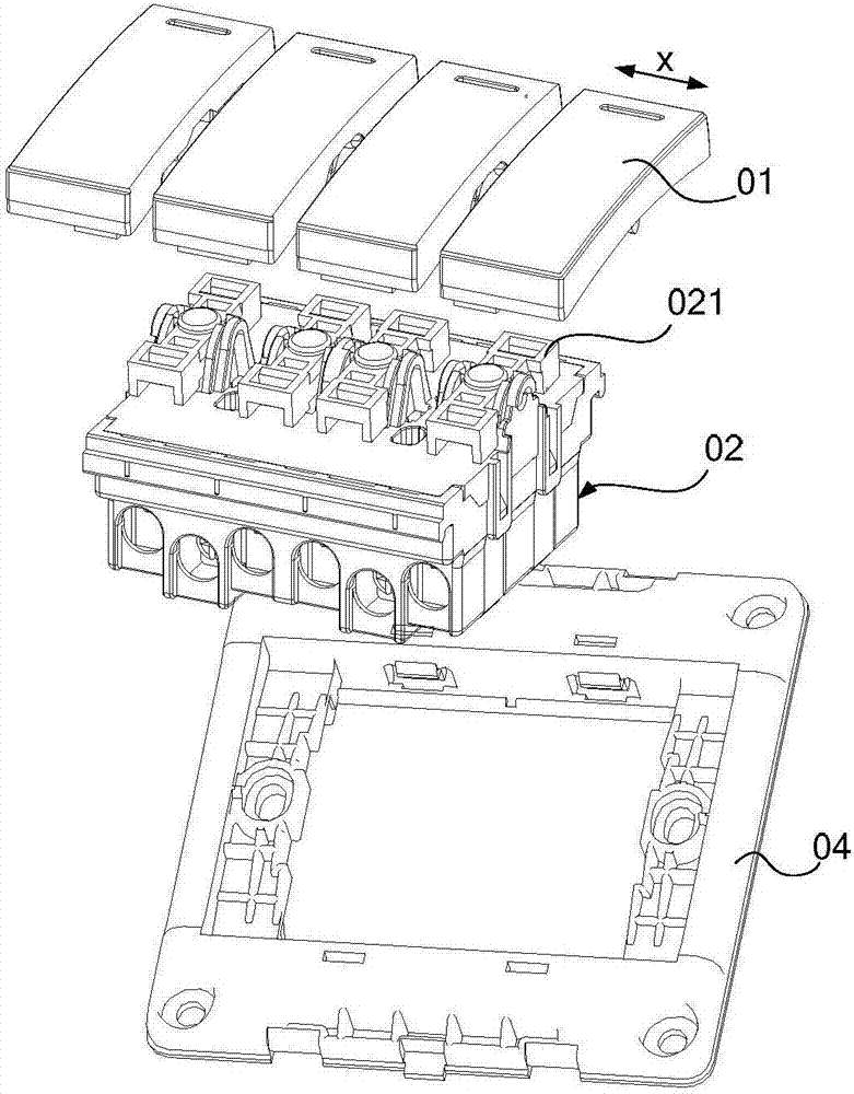
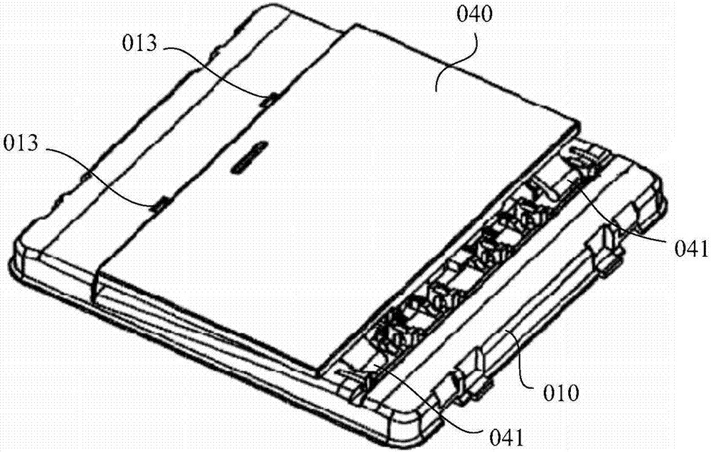
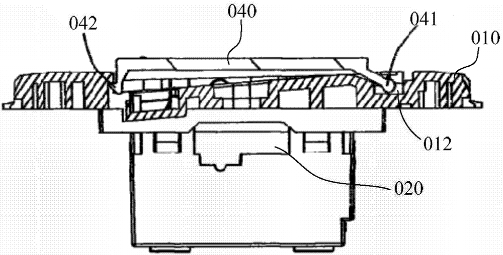
[0040] see Figure 4 with Figure 5 , the embodiment of the present invention provides a key switch, including a fixed frame 1, a functional component 2 and a button cover 3, the functional component 2 is connected to the fixed frame 1, and the functional component 2 includes a transition piece 21 (such as Figure 14 As shown), the button cover 3 is connected with the transition piece 21, and the opening and closing of the key switch can be realized through the transition piece 21. The area opposite to the button cover 3 on the fixed frame 1 is provided with a limit protrusion 4 (such as Figure 7 As shown), the inner walls of both ends of the button cover 3 along the width direction of the button cover 3 are in contact with the limit protrusion 4, and during the opening and closing movement of the button cover 3, the button cover 3 can move relative to the limit protrusion 4 slide.

[0041] It should be noted that: if Figure 4 As shown, the length direction of the button ...

Embodiment 2

[0060] The difference between the key switch of this embodiment and the first embodiment is that the limit protrusion 4 is not arranged on the fixed frame 1, but is arranged on the functional component 2, specifically, as Figure 14 with Figure 15 As shown, the area opposite to the button cover 3 on the functional component 2 is provided with a limit protrusion 4, and the inner wall surfaces of both ends of the button cover 3 along the width direction of the button cover 3 are in contact with the limit protrusion 4, and the button cover 3 is in contact with the limit protrusion 4. 3 During the opening and closing movement, the button cover 3 can slide relative to the limit protrusion 4. The beneficial effects achieved by the position-limiting protrusion 4 being arranged on the functional assembly 2 and the fixing frame 1 in the first embodiment are the same, and will not be repeated here.

[0061] Wherein, the position that the limit protrusion 4 is set is not unique, such ...


PUM


Abstract

The invention discloses a button switch, relating to the technical field of wall switch. The button switch is invented to solve the problem that the button cap is easy to swing to a certain extent in the width direction in the prior art. The embodiment of the invention provides a button switch. The button switch comprises a fixing frame, a function component and a button cap; the function component is connected with the fixing frame, and the functional component includes transition parts; the button cap is connected with the transition parts, and the switch can be opened and closed through the transition parts; a limiting bulge is arranged on the fixing frame in the area opposite to the button cap, or the limiting bulge is arranged on function component in the area opposite to the button cap; the inner wall of both ends of the button cap along the width direction is in contact with the limiting bulge, and the button cap can slide relatively to the limiting bulge in the opening and closing movement process of the button cap. The invention can be applied to wall switches.

Description

technical field [0001] The invention relates to the technical field of wall switches, in particular to a key switch. Background technique [0002] A wall switch is an electrical switch installed on the wall. It is a functional product for home decoration and is a household appliance used to connect and disconnect circuits. There are many types of wall switches, such as push button switches, rocker switches, etc. These switches are all provided with buttons, which are connected with functional components, and the switch can be turned on and off by the buttons. [0003] At present, most of the buttons of the wall switch (take the rocker switch as an example) are positioned by the transition pieces in the functional components, such as figure 1 As shown, the functional component 02 is fixed on the fixing frame 04, the button cover 01 is clamped on the transition piece 021 of the functional component 02, and the button cover 01 realizes the seesaw movement through the transitio...

Claims


Application Information

Patent Timeline
IPC IPC(8): H01H13/14
CPCH01H13/14
Inventor 王震彭美南
Owner NINGBO BULL ELECTRIC CO LTD
Why Eureka
Try Eureka