


Quick Research
Generate reliable direction feasibility study reports for your R&D in just a few steps.

Technical Q&A
Discover and master advanced knowledge NOW. Basics, ideas, possibilities, all at once.

Find Solutions
As an expert in R&D theories, this can generate solutions to your technical problems instantly.

Evaluate Feasibility
Analyze your overall solution with one click, know your potential R&D risks in advance.

Monitor Landscape
Get weekly tech updates, stay abreast of the latest tech innovations and key insights.
Sterile barrier assembly, mounting system, and method for coupling surgical components
A sterile barrier and installation system technology, which is applied in the direction of instruments, surgery, and surgical manipulators that provide a sterile surgical environment, and can solve problems such as deflection and bending, uneven compression of disinfection curtains, and inaccurate positioning
- Summary
- Abstract
- Description
- Claims
- Application Information
AI Technical Summary
Problems solved by technology
Method used
Image

Examples
Embodiment Construction
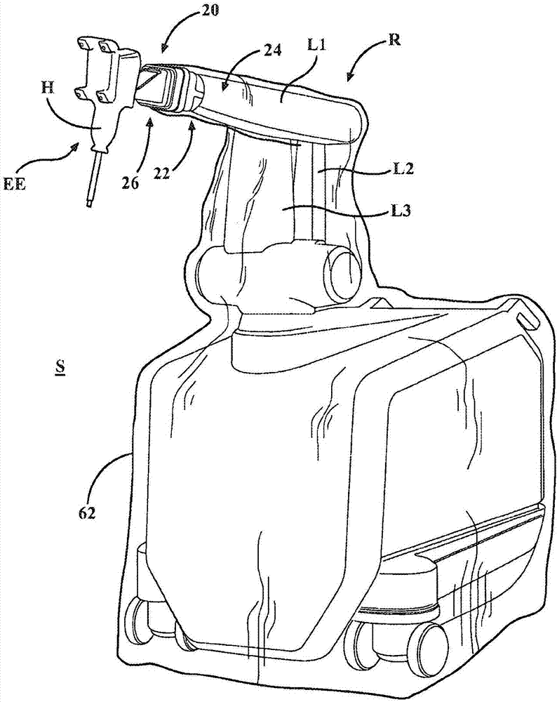
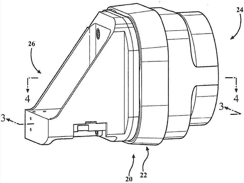
[0058] refer to figure 1 with 2 , shows a mounting system 20 for kinematically coupling a first surgical component and a second surgical component using a sterile barrier assembly 22 . In one embodiment described herein, the first surgical component is a robotic arm R and the second surgical component is an end effector EE for the robotic arm R. It should be appreciated that mounting system 20 may be employed to kinematically couple any surgical component using sterile barrier assembly 22 .
[0059] The robotic arm R includes a first mounting portion 24 and the end effector EE includes a second mounting portion 26 . Sterile barrier assembly 22 is positioned between first mounting portion 24 and second mounting portion 26 to establish a barrier between robotic arm R and end effector EE during surgery. This barrier separates the robotic arm R from the sterile field S in which the end effector EE operates. During surgery, the robotic arm R is considered non-sterile and the ba...
PUM
 Abstract
Description
Claims
Application Information
 - R&D Engineer
- R&D Manager
- IP Professional
- Industry Leading Data Capabilities
- Powerful AI technology
- Patent DNA Extraction
Browse by: Latest US Patents, China's latest patents, Technical Efficacy Thesaurus, Application Domain, Technology Topic, Popular Technical Reports.
© 2024 PatSnap. All rights reserved.Legal|Privacy policy|Modern Slavery Act Transparency Statement|Sitemap|About US| Contact US: help@patsnap.com