Supercharge Your Innovation With Domain-Expert AI Agents!

Narrow flake composite fiber material compression molding

A narrow sheet and fiber technology, applied in the field of compression molding of narrow sheet composite fiber materials, can solve problems such as orientation changes

Active Publication Date: 2017-10-17
THE BOEING CO
View PDF2 Cites 0 Cited by
  • Summary
  • Abstract
  • Description
  • Claims
  • Application Information

AI Technical Summary

Problems solved by technology

Although ultimately the sheets remain substantially stacked, as the laminated stack of sheets is pushed across the die, the orientation of the stack may change

Method used


Image

  • Narrow flake composite fiber material compression molding
  • Narrow flake composite fiber material compression molding
  • Narrow flake composite fiber material compression molding

Examples


Embodiment Construction

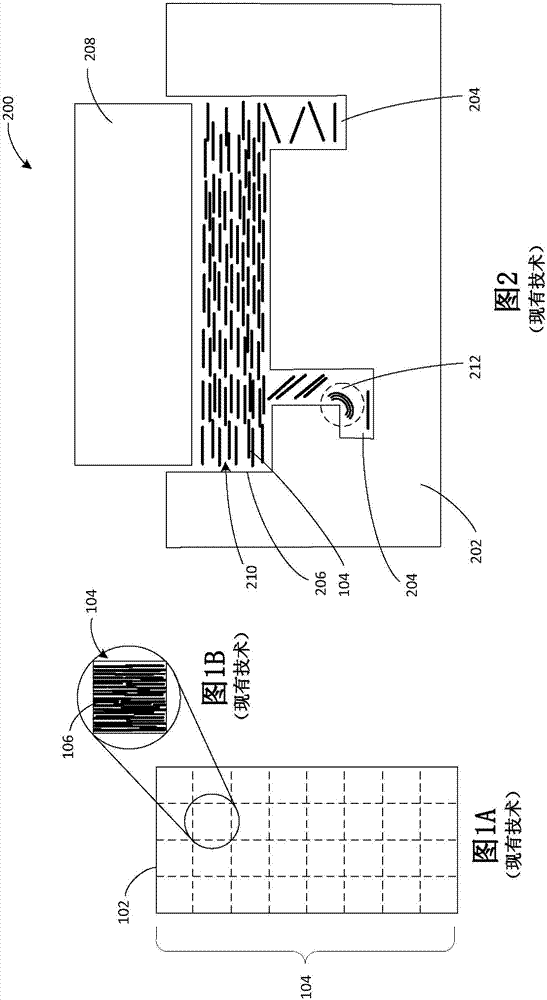
[0020] The detailed description below is directed to methods for producing three-dimensional random fiber orientations in composite components. As briefly discussed above, conventional composite assemblies made using compression molding techniques often include undesired areas of the laminate stack of composite sheets that have been pushed through the mold. The resulting assembly may include thinned regions corresponding to in-mold regions with substantially laminated stacks, particularly when these regions are subjected to shear or tensile forces during use of the composite assembly.

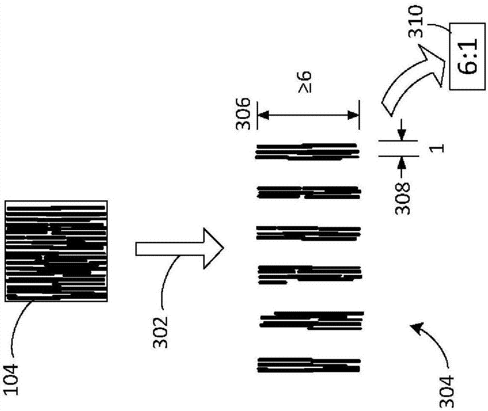
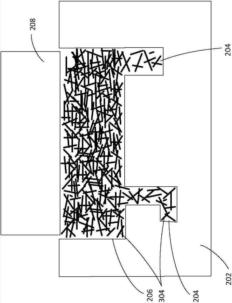
[0021] Utilizing the concepts described herein, composite components are fabricated in a manner that produces composite fibers with consistent, three-dimensionally random fiber orientation throughout the component. Doing so can increase the strength of the composite component, and most importantly, the strength of the component can be consistent and predictable throughout the component and all ...


PUM

PropertyMeasurementUnit
lengthaaaaaaaaaa
widthaaaaaaaaaa

Abstract

Methods provide for creating a three-dimensional random fiber orientation in a composite component. According to embodiments described herein, narrow flakes are created from a unidirectional composite fiber tape and poured into a reservoir of a mold, creating a three-dimensional random fiber orientation of the narrow flakes within the reservoir. At least a majority of the narrow flakes have an aspect ratio of length to width of at least 6:1. The narrow flakes are heated and compressed to fill the mold and create the composite component. The three-dimensional random fiber orientation of the narrow flakes within the reservoir is maintained as the narrow flakes are pushed through the mold, creating consistent, uniform strength characteristics throughout the resulting composite component.

Description

[0001] This application is a divisional application of Chinese patent application 201310024870.8 with a filing date of January 23, 2013 and an invention title of "compression molding of narrow sheet composite fiber materials". technical field [0002] This invention relates to compression molding of narrow sheet composite fibrous materials. Background technique [0003] Composite components are typically manufactured using thermoset or thermoplastic materials, which can be formed into strips or plates with carbon fibers, conventionally arranged in a unidirectional layout. The resulting unidirectional tape can be cut into smaller pieces or pieces, which are typically square or nearly square. The sheets are placed in a mold reservoir where heat and pressure are applied to force the sheets into all mold cavities. The resulting component is removed from the mold once plasticized. [0004] Conventional compression molding techniques can produce undesired variations in the stren...

Claims


Application Information

Patent Timeline
Patent Type & Authority Applications(China)
IPC IPC(8): B29C70/34B29C70/54
CPCB29C70/34B29C70/54B29C70/18B29C70/46B29C70/545Y10T428/24132B29B11/16B29C70/42B29C2793/0081B29C31/08B29C70/14B29C43/34
Inventor E·M·小费希尔D·L·科德B·A·卡特G·D·哈丁J·P·瑟伯D·E·贝利
Owner THE BOEING CO
Features
  • R&D
  • Intellectual Property
  • Life Sciences
  • Materials
  • Tech Scout
  • Unparalleled Data Quality
  • Higher Quality Content
  • 60% Fewer Hallucinations
Learn More