Supercharge Your Innovation With Domain-Expert AI Agents!

Cooling system used for supercharged engine and operation method of cooling system

A technology for supercharging engine and engine coolant, which is used in engine cooling, engine starting, engine components, etc., to solve the problems of increased time of fan high-speed operation, insufficient power, and engine power consumption, and to reduce global changes. Warming speed, improving power performance, and realizing the effect of fuel consumption

Active Publication Date: 2017-10-17
WEICHAI POWER CO LTD
View PDF4 Cites 2 Cited by
  • Summary
  • Abstract
  • Description
  • Claims
  • Application Information

AI Technical Summary

Problems solved by technology

In the fan control logic of most OEMs, only the water temperature of the engine coolant is monitored. When the fan rotates at a low speed, insufficient power and high fuel consumption are likely to occur due to the high temperature of the intercooler air.
The fan control logic of some OEMs will monitor the temperature of the intercooler air. In this case, the time for the fan to run at high speed increases, and the fuel saving effect becomes worse.
In addition, when driving in winter, the water temperature rises slowly, and the temperature of the intercooler air will quickly rise to above 100°C. If the fan is turned on, the cold air sucked by the fan will cool the intercooler and take away the temperature of the engine at the same time, resulting in a hot car. The time becomes longer, so that the engine will work in a cold car state for a long time; if the fan is not turned on, the temperature of the intercooled air entering the engine will be high, both of which are not conducive to the combustion and reliability of the engine
[0003] At present, many vehicles use flexible fans. The flexible fans have two control modes: one is to monitor the water temperature only, and the fan does not rotate or rotates slowly when the water temperature is low. If the temperature is high, the combustion will deteriorate; the other is to monitor the water temperature and the intake air temperature of the engine at the same time. Low, not conducive to engine combustion and lubrication, while the fan consumes engine power and increases fuel consumption

Method used


Image

  • Cooling system used for supercharged engine and operation method of cooling system
  • Cooling system used for supercharged engine and operation method of cooling system
  • Cooling system used for supercharged engine and operation method of cooling system

Examples


Embodiment Construction

[0026] Exemplary embodiments of the present disclosure will be described in more detail below with reference to the accompanying drawings. Although exemplary embodiments of the present disclosure are shown in the drawings, it should be understood that the present disclosure may be embodied in various forms and should not be limited by the embodiments set forth herein. Rather, these embodiments are provided for more thorough understanding of the present disclosure and to fully convey the scope of the present disclosure to those skilled in the art.

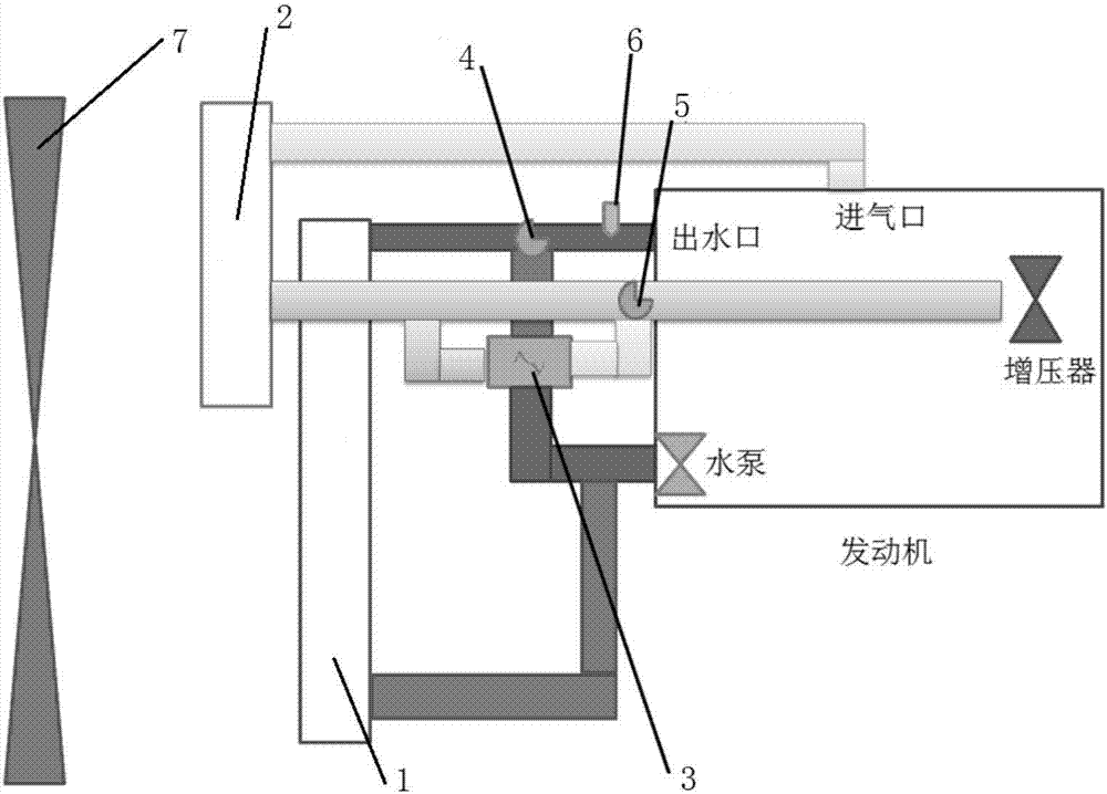
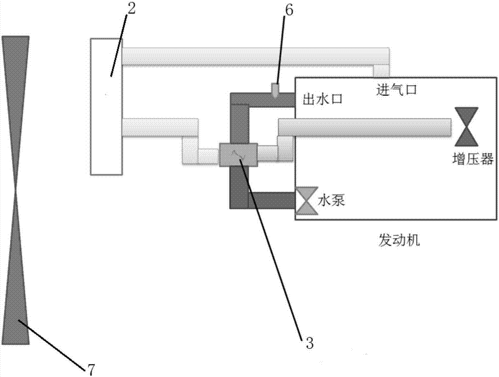
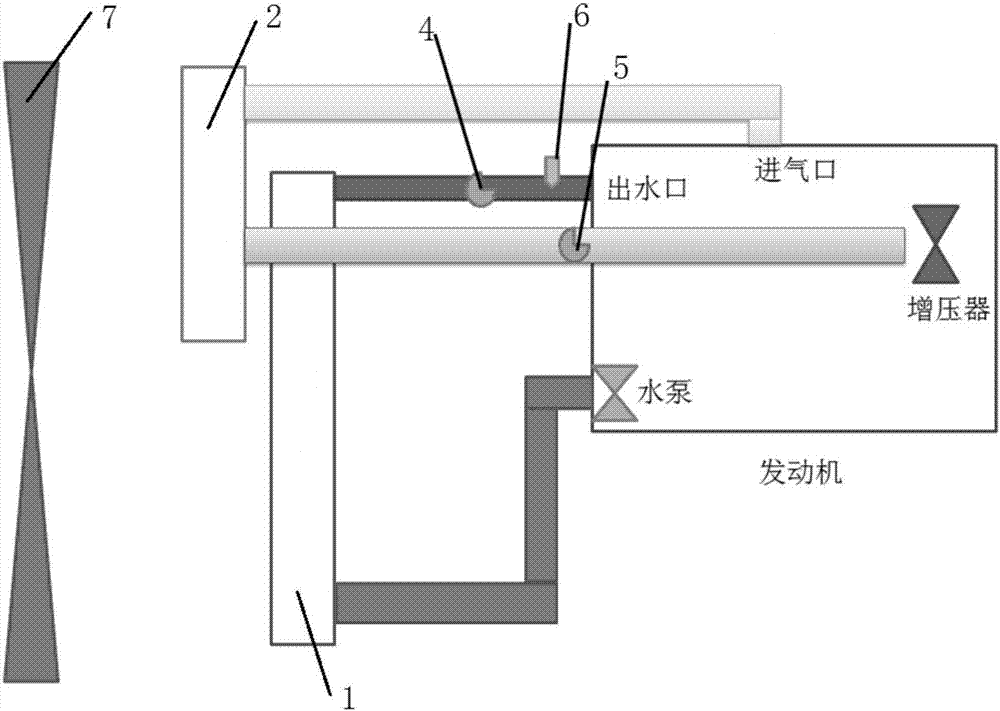
[0027] According to the embodiment of the present invention, such as figure 1As shown, a cooling system for a supercharged engine is proposed, the cooling system includes an engine coolant circulation subsystem and a charge air circulation subsystem; the engine coolant circulation subsystem includes a radiator 1 for cooling the engine coolant and coolant thermostat 4, the charge air circulation subsystem includes an intercooler 2 a...


PUM


Abstract

The invention relates to a cooling system used for a supercharged engine and an operation method of the cooling system. The cooling system comprises an engine coolant circulation subsystem and a supercharged air circulation subsystem; the engine coolant circulation subsystem comprises a coolant thermostat and a radiator for cooling an engine coolant; the supercharged air circulation subsystem comprises a supercharged air thermostat and an intercooler for cooling supercharged air; the cooling system further comprises a fan for cooling the intercooler and the radiator, a temperature sensor arranged at a water outlet of the engine and a heat exchanger for enabling the supercharged air and the engine coolant to conduct heat exchange; and the supercharged air thermostat is an electronic thermostat connected with the temperature sensor.

Description

technical field [0001] The invention relates to the field of engine technology, in particular to a cooling system for a supercharged engine and an operating method thereof. Background technique [0002] At present, most of the cooling systems on commercial vehicles and construction machinery include engine coolant radiators and intercoolers. Among them, the intercooler reduces the temperature of the high-temperature air after the supercharged engine is supercharged, so as to reduce the heat load of the engine and increase the air intake. , thereby increasing the power of the engine and reducing fuel consumption. In order to reduce the fuel consumption of the whole vehicle, a flexible fan (that is, a fan that can adjust the air volume according to the demand for heat dissipation, generally by adjusting the speed ratio of the fan and the crankshaft to adjust the air volume) is generally selected as the cooling air power source of the heat dissipation system on the vehicle. Wh...

Claims


Application Information

Patent Timeline
Patent Type & Authority Applications(China)
IPC IPC(8): F01P7/16F01P7/02F01P7/04F01P11/16F02B29/04F02N19/10
CPCF01P7/026F01P7/04F01P7/165F01P11/16F01P2037/02F01P2060/02F02B29/0443F02B29/0493F02N19/10Y02T10/12
Inventor 曹原李荣光梁昌水邬忠永范明果
Owner WEICHAI POWER CO LTD
Features
  • R&D
  • Intellectual Property
  • Life Sciences
  • Materials
  • Tech Scout
  • Unparalleled Data Quality
  • Higher Quality Content
  • 60% Fewer Hallucinations
Learn More