An optical structure, its control method, and a display device

A control method and optical structure technology, applied in the field of optics, can solve problems such as inconvenient operation, achieve good user experience and improve user experience

Active Publication Date: 2021-04-13
BOE TECH GRP CO LTD +1
View PDF6 Cites 0 Cited by
  • Summary
  • Abstract
  • Description
  • Claims
  • Application Information

AI Technical Summary

Problems solved by technology

[0004] The invention provides an optical structure, its control method, and a display device, which are used to solve the problem of inconvenient operation by manually adjusting the voltage applied to the polymer dispersed liquid crystal to adjust the light transmittance

Method used


Image

  • An optical structure, its control method, and a display device
  • An optical structure, its control method, and a display device
  • An optical structure, its control method, and a display device

Examples


Embodiment 1

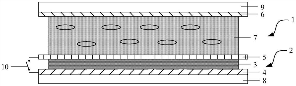
[0045] combine Figure 1-Figure 3 As shown, this embodiment provides an optical structure, including:

[0046] A dimming unit 1, the dimming unit 1 includes at least two sub-areas;

[0047] At least two optical sensing units 2, the optical sensing units 2 are arranged on the surface of the dimming unit 1, and correspond to the positions of the sub-regions one by one, and each optical sensing unit 2 is used to obtain the illumination corresponding to the Parameters related to the light intensity of the sub-area;

[0048] The control unit is connected with the optical sensing unit 2 and the dimming unit 1, and is used for controlling the light transmittance of the corresponding sub-region according to parameters related to the light intensity irradiating each sub-region.

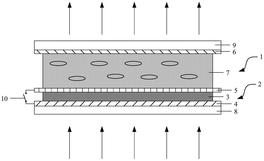
[0049] The above optical structure obtains parameters related to light intensity by setting an optical sensing unit, and controls the light transmittance of the dimming unit according to the parameters relat...

Embodiment 2

[0104] combine Figure 1-Figure 3 As shown, this embodiment provides a method for controlling the optical structure in Embodiment 1, including:

[0105] providing a dimming unit 1, dividing the dimming unit 1 into at least two sub-areas;

[0106] Acquiring parameters related to the illumination intensity of each sub-area of ​​the irradiated dimming unit 1;

[0107] The light transmittance of the corresponding sub-region is controlled according to the parameters related to the light intensity irradiating each sub-region.

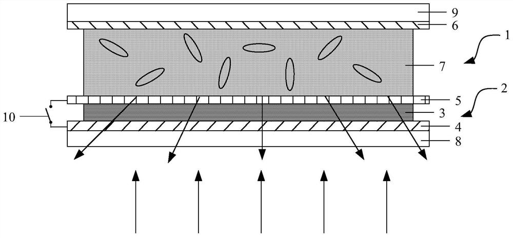
[0108] The above control method automatically controls the light transmittance of the optical structure according to the light intensity, thereby improving user experience. At the same time, the dimming unit is controlled in partitions, and the light transmittance of the corresponding sub-area is controlled according to the parameters related to the light intensity irradiating each sub-area, which can ensure that the light transmittance of the entire dimmin...


PUM


Abstract

The invention relates to the field of optical technology, and discloses an optical structure, a control method thereof, and a display device. The optical structure includes a dimming unit, an optical sensing unit and a control unit. The dimming unit is divided into at least two sub-regions, the optical sensing unit is used to obtain parameters related to the light intensity irradiating each sub-region of the dimming unit, and the control unit illuminates each sub-region according to The parameters related to light intensity control the light transmittance of the corresponding sub-area, so that the light transmittance of the optical structure can be automatically adjusted according to the light intensity without manual adjustment, which improves user experience. At the same time, the divisional control of the dimming unit can ensure that the light transmittance of the entire dimming unit is the same to obtain a better user experience.

Description

technical field [0001] The invention relates to the field of optical technology, in particular to an optical structure, a control method thereof, and a display device. Background technique [0002] Polymer Dispersed Liquid Crystal (Polymer Dispersed Liquid Crystal, referred to as PDLC) is a mixture of low-molecular liquid crystals and prepolymers, and undergoes polymerization under certain conditions to form micron-sized liquid crystal droplets that are evenly dispersed in the polymer network. The dielectric anisotropy of liquid crystal molecules is used to obtain materials with electro-optic response characteristics. PDLC has two working states of scattering state and transparent state, and has a certain gray scale, so it has received extensive attention and has broad application prospects. [0003] The preparation process of PDLC devices is simple, and it has been widely used in large-area flexible displays, optical modulators, heat-sensitive and pressure-sensitive device...

Claims


Application Information

Patent Timeline
Patent Type & Authority Patents(China)
IPC IPC(8): G02F1/133G02F1/1343G02F1/1334
CPCG02F1/13318G02F1/1334G02F1/1343E06B3/6722G02F1/13306G02F1/135G02F2201/58G02F2203/30G02F2203/48G02F1/133618G02F1/134309
Inventor 郭远辉黄钢琪
Owner BOE TECH GRP CO LTD
Why Eureka
Try Eureka