Dimming box, display panel and driving method

A display panel and dimming technology, which is applied in optics, static indicators, nonlinear optics, etc., can solve the problems of poor display quality and uneven layout of touch lines on the display panel, and achieve improved image quality and light transmission. over rate same effect

Active Publication Date: 2022-04-22
KUSN INFOVISION OPTOELECTRONICS
View PDF4 Cites 0 Cited by
  • Summary
  • Abstract
  • Description
  • Claims
  • Application Information

AI Technical Summary

Problems solved by technology

[0006] In order to overcome the shortcomings and deficiencies in the prior art, the purpose of the present invention is to provide a dimming box, a display panel and a driving method to solve the problem of uneven arrangement of touch lines in the display panel of the prior art, which causes the display picture poor quality problem

Method used


Image

  • Dimming box, display panel and driving method
  • Dimming box, display panel and driving method
  • Dimming box, display panel and driving method

Examples


Embodiment 1

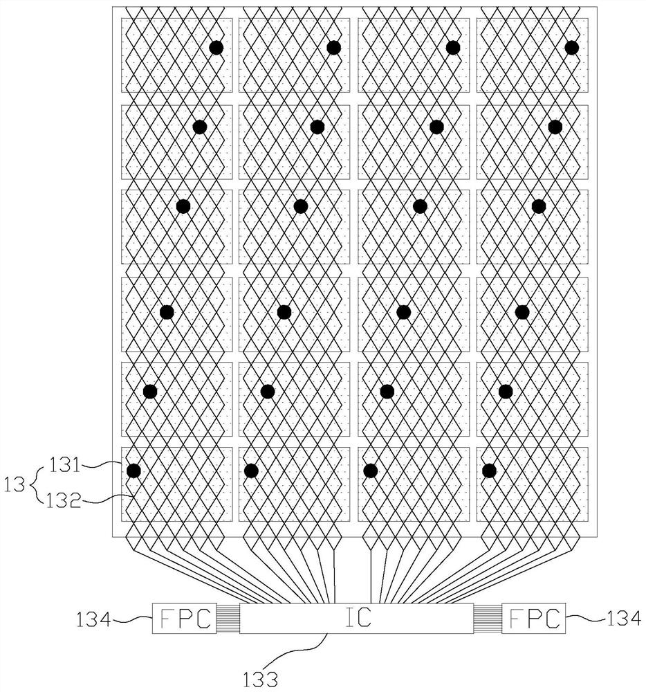
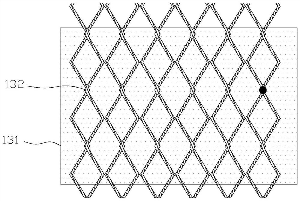
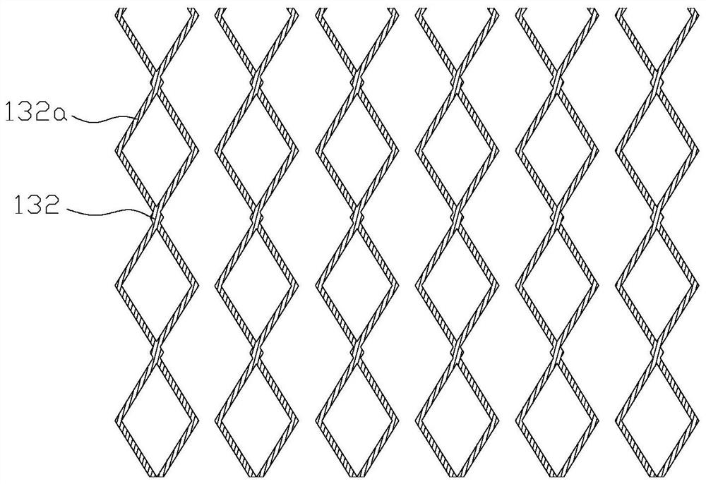
[0038] figure 1 is a schematic plan view of the touch electrode layer in the present invention, figure 2 It is a schematic diagram of the enlarged structure of the touch electrode layer in a touch electrode block area in Embodiment 1 of the present invention, image 3 is a schematic plan view of the touch wiring in Embodiment 1 of the present invention, Figure 4 It is a schematic diagram of the structure of the display panel at a wide viewing angle in Embodiment 1 of the present invention, Figure 5 It is a structural schematic diagram of the display panel in the narrow viewing angle in Embodiment 1 of the present invention.

[0039] Such as Figure 1 to Figure 5 As shown, a display panel provided by Embodiment 1 of the present invention includes a color filter substrate 10 , an array substrate 20 disposed opposite to the color filter substrate 10 , and a first liquid crystal layer 30 located between the color filter substrate 10 and the array substrate 20 . The first l...

Embodiment 2

[0050] Such as Figure 6 and Figure 7 As shown, the display panel provided by Embodiment 2 of the present invention is the same as Embodiment 1 ( Figure 1 to Figure 5 ) are basically the same, the difference is that in this embodiment, the display panel includes a display liquid crystal box and a dimming box for controlling the viewing angle, and the display liquid crystal box includes a color filter substrate 10 opposite to the color filter substrate 10 The arranged array substrate 20 and the first liquid crystal layer 30 between the color filter substrate 10 and the array substrate 20, the dimming box includes a first substrate 50, a second substrate 60 opposite to the first substrate 50, and a 50 and the second liquid crystal layer 70 between the second substrate 60 . The display liquid crystal box is preferably arranged below the dimming box, and the display liquid crystal box may also be arranged above the dimming box. Wherein, the first substrate 50 and the second s...

Embodiment 3

[0059] Such as Figure 8 and Figure 9 As shown, the display panel provided by Embodiment 3 of the present invention is the same as Embodiment 1 ( Figure 1 to Figure 5 ) are basically the same display panel, the difference is that in this embodiment, the touch electrode block 131 is provided with a plurality of through holes 131a, the through holes 131a are prismatic frame structures, and the width of the through holes 131a is 5um- The through holes 131a arranged in a whole row or column are connected to each other, and the electrode blocks in the frame of the prismatic through holes 131a are relatively isolated and are not used for applying touch signals.

[0060] Compared with Embodiment 1, in this embodiment, the touch electrode block 131 is made into a patterned structure to reduce the area of ​​the actual working area of ​​the touch electrode block 131, which can reduce the charging amount of the touch electrode block 131, so as to reduce the Small touch delay.

[006...


PUM


Abstract

The invention discloses a display panel, comprising a display liquid crystal box, the display liquid crystal box includes a color filter substrate, an array substrate opposite to the color filter substrate, and a first liquid crystal layer located between the color filter substrate and the array substrate, and the color filter substrate A touch electrode layer and a viewing angle control electrode are provided on the side facing the first liquid crystal layer, and a common electrode is provided on the array substrate facing the first liquid crystal layer. The touch electrode layer includes a plurality of touch electrode blocks and a plurality of The touch traces, the plurality of touch electrode blocks are electrically connected to the touch chip through the touch traces, and each touch trace corresponds to a whole row or column of touch electrode blocks. By designing each touch wire to correspond to a whole row or column of touch electrode blocks, the touch wires are evenly arranged on the entire surface of the display panel, so that the light on the entire surface of the display panel is transparent. The pass rate is the same to avoid affecting the normal display of the screen and increase the display quality. The invention also discloses a dimming box and a driving method.

Description

technical field [0001] The invention relates to the technical field of liquid crystal display, in particular to a dimming box, a display panel and a driving method. Background technique [0002] Liquid crystal display (liquid crystal display, LCD) has the advantages of good image quality, small size, light weight, low driving voltage, low power consumption, no radiation and relatively low manufacturing cost, and occupies a dominant position in the field of flat panel display. The liquid crystal display device includes a color filter substrate and a thin film transistor array substrate oppositely arranged, and a liquid crystal layer sandwiched between them. [0003] Currently, liquid crystal display devices are gradually developing toward wide viewing angles. For example, liquid crystal display devices using in-plane switching (IPS) or fringe field switching (FFS) modes can achieve wider viewing angles. However, in today's society, people pay more and more attention to prote...

Claims


Application Information

Patent Timeline
Patent Type & Authority Patents(China)
IPC IPC(8): G02F1/1343G02F1/1333G02F1/13G02F1/133G06F3/041
CPCG02F1/134309G02F1/13338G02F1/1323G02F1/13306G06F3/0412
Inventor 邱峰青谢颖颖夏鹏程魏祥利
Owner KUSN INFOVISION OPTOELECTRONICS
Why Eureka
Try Eureka