Uniformity restoration method after brightness correction of LED display screen

A technology of LED display and brightness correction, applied to static indicators, instruments, etc., can solve problems such as inaccurate calibration, dark on both sides, dark in the middle, bright on both sides, dark in the middle, etc.

Active Publication Date: 2017-10-17
CHANGCHUN CEDAR ELECTRONICS TECH CO LTD
View PDF5 Cites 17 Cited by
  • Summary
  • Abstract
  • Description
  • Claims
  • Application Information

AI Technical Summary

Problems solved by technology

[0008] Although this method can improve the acquisition accuracy, due to the consumption of the acquisition equipment, changing the focusing lens, photoelectric sensor, or changing a new set of calibration equipment, each change of the acquisition equipment will lead to inaccurate calibration, which requires a new calibration, which greatly Increased costs and reduced efficiency
At the same time, although the problem of inaccurate acquisition equipment has been solved, due to the luminous characteristics of the LED, the imaging characteristics of the optical system and the acquisition method and other factors will still cause some areas to appear bright in the middle and dark on both sides or dark on both sides after brightness correction. exist
The traditional image grayscale restoration algorithm only repairs the grayscale image, while each pixel in the LED display brightness correction coefficient map has a specific proportional relationship and cannot be changed arbitrarily, so the application of the traditional image grayscale restoration algorithm will mosaic phenomenon

Method used


Image

  • Uniformity restoration method after brightness correction of LED display screen
  • Uniformity restoration method after brightness correction of LED display screen
  • Uniformity restoration method after brightness correction of LED display screen

Examples


Embodiment Construction

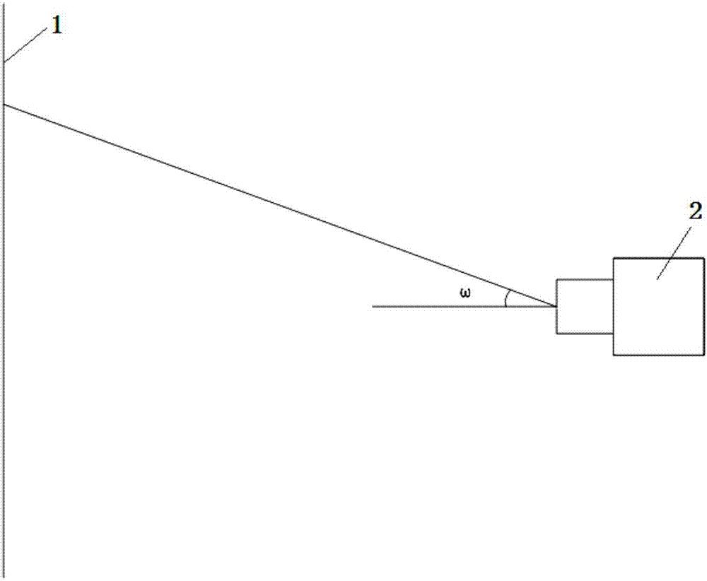
[0064] To calibrate the brightness of the LED display with the calibration equipment, it is first necessary to place the acquisition device 2 in front of the LED display 1 to collect the brightness parameters of the display, such as figure 1 As shown (ω in the figure is the incident angle of light collected by the LED at the off-axis point), the relative brightness values ​​of red, green and blue colors of each LED light on the display screen are obtained, and then the respective correction coefficients are calculated according to the relative brightness values, and uploaded data and save it. Due to factors such as the inaccuracy of the acquisition equipment itself and optical imaging in the brightness correction acquisition system of the LED display, it will lead to the generation of the corrected curved surface.

[0065] The present invention realizes the uniformity restoration after the brightness correction of the LED display screen through the programming of the upper com...


PUM


Abstract

The invention relates to a uniformity restoration method after the brightness correction of an LED display screen, and the method comprises the steps: taking a correction coefficient map of red, green and blue colors as the basis, carrying out the gray scale processing of the correction coefficient map, obtaining a region with the inconsistent uniformity after brightness correction, carrying out the mapping of the region to the original correction coefficient map, carrying out the processing of the gray scale values of pixels in the region of the original correction coefficient map through a step-by-step weighting progressive change shrinkage algorithm, obtaining the corrected gray scale value of each pixel, replacing the correction coefficient of the region in the original correction coefficient map, and uploading the coefficient to the LED display screen for storage. According to the invention, an upper computer is taken as a development platform, and the method achieves a purpose of correction uniformity restoration through the correction of the corrected coefficient map, reduces the requirements for collection equipment and a collection mode, facilitates the engineering application, and saves the cost.

Description

technical field [0001] The invention belongs to the field of LED display correction technology and image processing, and relates to a uniformity repair method after brightness correction of an LED display screen. Background technique [0002] As a multimedia display terminal, the display effect of LED display is an important indicator to measure its quality, among which the uniformity of brightness display is the most important. Due to the discreteness and attenuation of light-emitting diodes, the LED display has the problem of uneven brightness display, which seriously affects the display effect. In order to overcome this problem, the point-by-point brightness correction technology of LED display screens emerged at the historic moment, and developed rapidly, which greatly improved the display quality. [0003] The commonly used LED point-by-point correction technology is to collect the display screen point by point through industrial cameras (CCD or CMOS) or SLR cameras, a...

Claims


Application Information

Patent Timeline
Patent Type & Authority Applications(China)
IPC IPC(8): G09G3/32
CPCG09G3/32G09G2320/0666
Inventor 毛新越王瑞光程宏斌苗静
Owner CHANGCHUN CEDAR ELECTRONICS TECH CO LTD
Why Eureka
Try Eureka