Eureka AIR delivers breakthrough ideas for toughest innovation challenges, trusted by R&D personnel around the world.

Axial flow turbine

A technology of axial-flow turbines and fluids, applied in non-variable engines, mechanical equipment, engine components, etc., to achieve the effect of reducing short-circuit loss and leakage loss, and increasing rotation rate

Inactive Publication Date: 2017-10-17
崔爀善
View PDF7 Cites 0 Cited by
  • Summary
  • Abstract
  • Description
  • Claims
  • Application Information

AI Technical Summary

Problems solved by technology

[0005] However, it is difficult for such an axial flow turbine to minimize the loss from the main flow exceeding due to the collision of the fluid with the blades or the leakage loss and the short circuit loss

Method used


Image

  • Axial flow turbine
  • Axial flow turbine
  • Axial flow turbine

Examples


Embodiment Construction

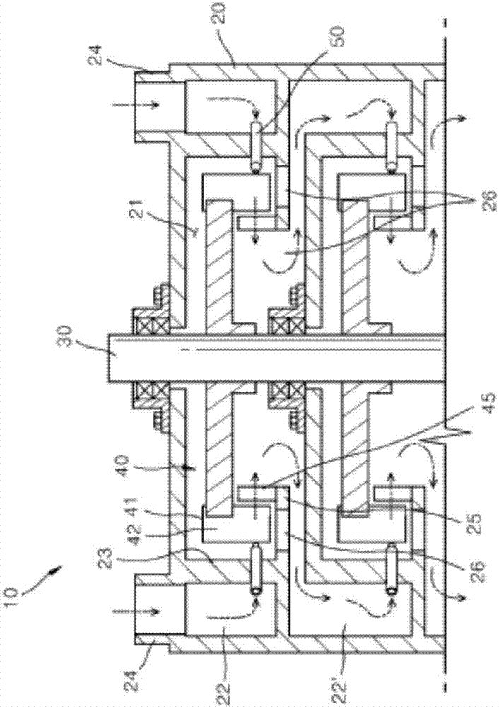
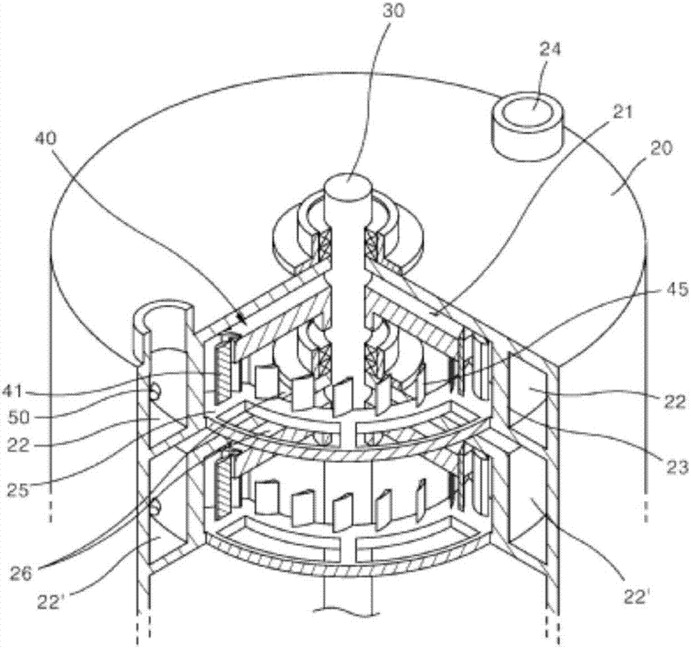
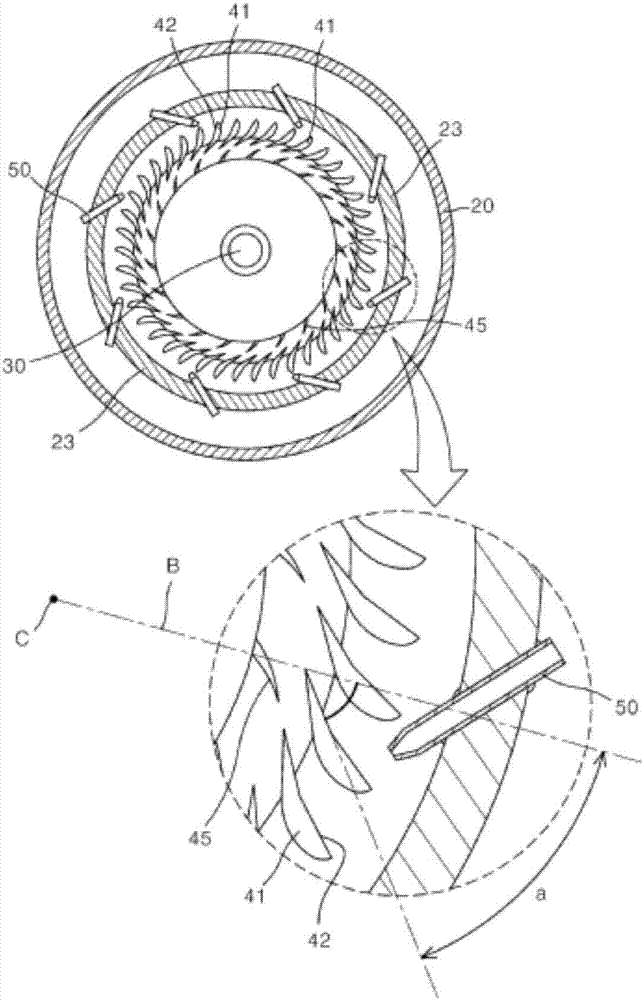
[0024] An embodiment of the axial turbine of the present invention is presented in Figure 1 to Figure 4 .

[0025] With reference to the drawings, the axial turbine 10 of the present invention includes: a housing 20 in which a rotor mounting portion 21 is formed, and the rotor mounting portion 21 and a fluid supply portion 22 partitioned by partition walls 23 are formed; the rotor 40 is provided in the above The rotating shaft 30 provided in the housing 20 is provided on the rotor mounting portion 21 to install a plurality of blades 41 along the circumferential direction; and a plurality of nozzles 50 are provided on the partition wall 23 and spray to the fluid collision surface 42 of the blade 41 The fluid supplied to the fluid supply unit 22 causes the rotor 40 to rotate.

[0026] A plurality of rotor mounting parts 21 of the housing 20 are stacked in the vertical direction of the rotating shaft 30 inside the housing 20, and a rotor 40 is provided in each rotor mounting part 21...


PUM


Abstract

The present invention relates to an axial flow turbine, comprising: a rotor mounting part; a housing having a fluid supply part surrounding the rotor mounting part; a rotor which is installed at a rotation shaft installed in the housing and has a plurality of blades installed in a circumferential direction; and a plurality of injection nozzles, installed in the fluid supply part surrounding the rotor mounting part, for spraying a high-pressure fluid toward the blades, wherein the fluid collision surface of the blades installed at the rotor is formed to be inclined at an angle in the rotational direction of the rotor with respect to the normal axis of the rotation center axis, and the injection nozzles formed in the fluid supply part are installed at an angle parallel to the normal direction of the fluid collision surface of the blades. Due to the aforementioned configuration, the present invention provides the effect of maximizing the rotation rate of a turbine while smoothing fluid flow by optimizing the angle of the fluid collision surface of the blades.

Description

Technical field [0001] The present invention relates to an axial flow turbine, and more specifically, an axial flow turbine in which the blade angle of the rotor is improved. Background technique [0002] Generally, gas turbines or steam turbines used for power generation panels and the like are divided into axial flow turbines in which fluid flows in the direction of the rotation axis of the turbine, diagonal flow turbines in which fluid flows from the rotation axis, and fluid to the rotation diameter Radial turbines flowing in the direction. Among them, in particular, axial flow turbines are suitable for large-capacity power generation panels, and thus are widely used in steam turbines and the like in thermal power plants. [0003] From the viewpoint of economical improvement and environmental load reduction, this axial-flow turbine needs to increase the power generation efficiency of the additional layer of the power generation board, and the high performance of the turbine is ...

Claims


Application Information

Patent Timeline
Patent Type & Authority Applications(China)
IPC IPC(8): F01D1/08F01D1/10F01D5/14F01D9/04
CPCF01D1/08F01D1/10F01D5/14F01D9/04F01D1/22F01D5/142F01D5/025F01D9/041F01D1/026F01D9/045
Inventor 崔爀善
Owner 崔爀善
Why Eureka
Eureka Blog
Learn More