
Rotary core-pulling device for outer deep undercut of fixed mold side of injection mold

An injection mold and core-pulling technology, which is applied in the field of deep-reverse rotary core-pulling devices on the fixed mold side of the injection mold, can solve the problems of large internal space, many links, and complex structure in the mold.

Inactive Publication Date: 2017-10-20
NINGBO YUEFEI MOLD
View PDF0 Cites 0 Cited by
  • Summary
  • Abstract
  • Description
  • Claims
  • Application Information

AI Technical Summary

Problems solved by technology

[0003] For the external deep undercut core-pulling on the fixed mold side, the existing technology uses the oil cylinder to drive the core-pulling block to rotate the core-pulling through the rack and gear, which is referred to as the rack method. Since the work of the oil cylinder involves hydraulic source, oil circuit, and control, the structure is complicated , many links, many potential failure nodes, high failure rate, poor reliability, and high operation and maintenance costs. In addition, the rack method occupies a large internal space of the mold, resulting in a large mold shape and high manufacturing costs; therefore, the existing technology has a complex structure , poor reliability, high cost problems and deficiencies

Method used


Image

  • Rotary core-pulling device for outer deep undercut of fixed mold side of injection mold
  • Rotary core-pulling device for outer deep undercut of fixed mold side of injection mold
  • Rotary core-pulling device for outer deep undercut of fixed mold side of injection mold

Examples


Embodiment Construction

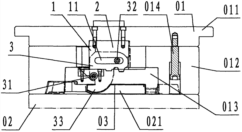
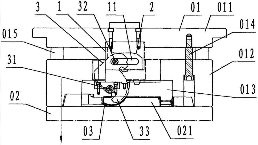
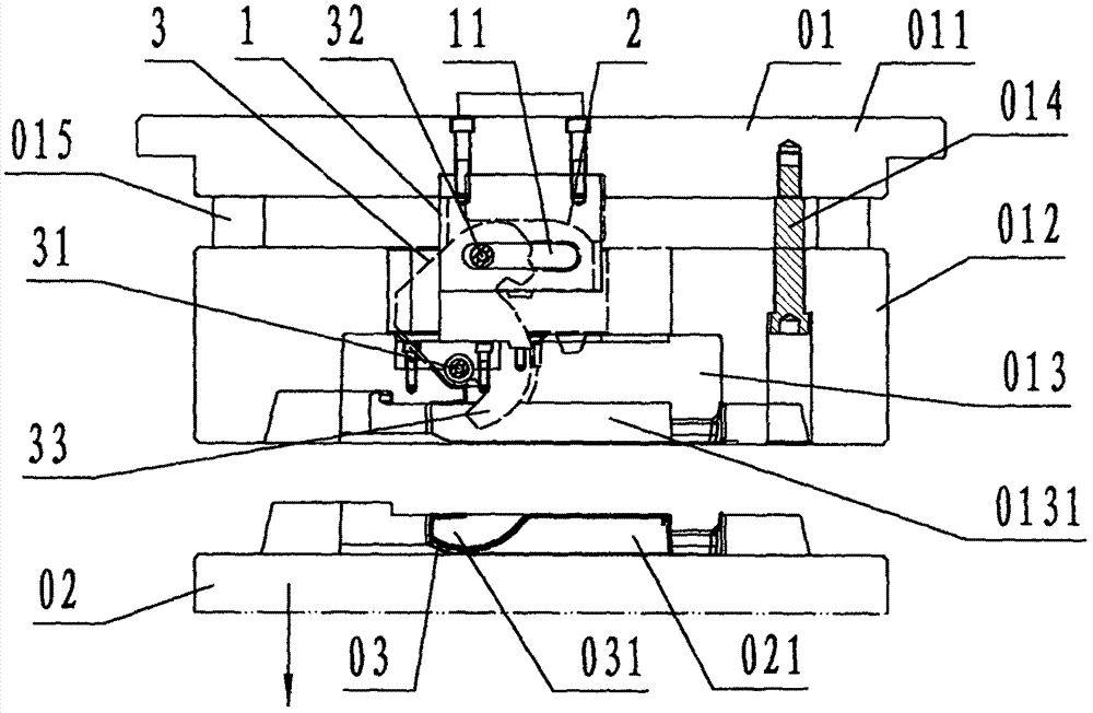
[0023] refer to Figure 1 to Figure 4 , a deep undercut rotary core-pulling device on the fixed mold side of the injection mold of the present invention, comprising a pull plate 1, a pressing block 2 and a deep buckle core block 3, wherein: the pull plate 1 is a rectangular plate-shaped steel Components, the lower part of the pull plate 1 is provided with a through hole in the shape of a horizontal oblong and the direction is the front and rear direction, which is called the guide hole 11;

[0024] The briquetting block 2 is an elongated block-shaped steel member that is rectangular in plan view and whose long side is in the front-rear direction. The bottom of the briquetting block 2 is provided with a shape corresponding to the top of the deep buckle core block 3;

[0025] The deep buckle core block 3 is a J-shaped hook-shaped main view, and a long block-shaped steel member whose long side is the front and rear direction when viewed from above. Cylindrical guide pin 32, the ...


PUM


Abstract

The invention discloses a deep undercut rotary core-pulling device on the fixed side of an injection mold, which comprises a pulling plate (1), a pressing block (2) and a deep buckling core block (3). The pull plate adopted in the present invention is provided with guide holes, and the deep buckle core block is provided with a rotating shaft and a guide pin. The deep buckle core block is connected with the cavity block through the rotating shaft, and the reverse end of the deep buckle core block is located in the cavity; two The drawing plates are respectively located on the front and rear sides of the deep buckle core block, and the drawing plate is fixedly connected with the panel of the fixed mold; the guide pin of the deep buckle core block is inserted in the guide hole of the drawing plate, and the pressing block is fixedly connected with the fixed mold panel The top of the deep buckle core block is in contact; when working, the fixed mold carrier plate and the fixed mold panel are separated first, and the pull plate pulls the deep buckle core block through the guide hole and guide pin to rotate counterclockwise around the rotating shaft, so that the undercut end is free from the product. The outer deep undercut is rotated and core-pulled out, and then the movable mold and the fixed mold are separated to release the product. The rotary core-pulling of the outer deep undercut on the fixed mold side of the plastic mold achieves simplified structure and work. Reliability and cost reduction purposes.

Description

technical field [0001] The invention relates to a core-pulling and demoulding device for an injection mold, in particular to a deep undercut on the fixed side of an injection mold for core-pulling and demoulding for the deep undercut of a product on the fixed side of the injection mold Rotary core puller. Background technique [0002] Explanation: Undercut refers to the flange, hook or rib structure in which the direction of core pulling and demoulding intersects with the opening and closing direction of the mold in injection molded products; the side facing the outside world when injection molded products are applied is called the outside, which is opposite to the outside The other side of the product is called the inner side; according to the position, the undercut located on the outside of the product is called the outer undercut, and the undercut located on the inside of the product is called the inner undercut; according to the size, the depth or length of the undercut ...

Claims


Application Information

Patent Timeline
IPC IPC(8): B29C45/33B29C45/44
CPCB29C45/33B29C45/44
Inventor 谢青文赵志超张跃飞
Owner NINGBO YUEFEI MOLD
Learn More