
Printing head self-adaptive adjustment device and printer thereof

A self-adaptive adjustment and adjustment device technology, applied in power transmission devices, printing, transfer materials, etc., can solve problems such as the difficulty in adjusting the parallelism between the print head and the rubber roller, achieve stable locking, uniform pressure, and ensure stability Effect

Active Publication Date: 2017-10-20
XIAMEN HANIN ELECTRONICS TECH CO LTD
View PDF7 Cites 3 Cited by
  • Summary
  • Abstract
  • Description
  • Claims
  • Application Information

AI Technical Summary

Problems solved by technology

[0003] The present invention provides a printing head self-adaptive adjustment device, aiming to improve the existing problem of difficulty in adjusting the parallelism between the printing head and the rubber roller
[0004] The present invention provides a printer, which aims to improve the existing difficulty in adjusting the parallelism between the print head and the rubber roller

Method used


Image

  • Printing head self-adaptive adjustment device and printer thereof
  • Printing head self-adaptive adjustment device and printer thereof
  • Printing head self-adaptive adjustment device and printer thereof

Examples


Embodiment 1

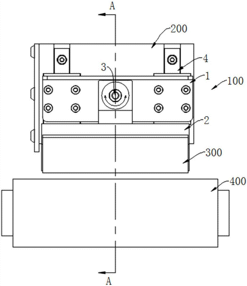
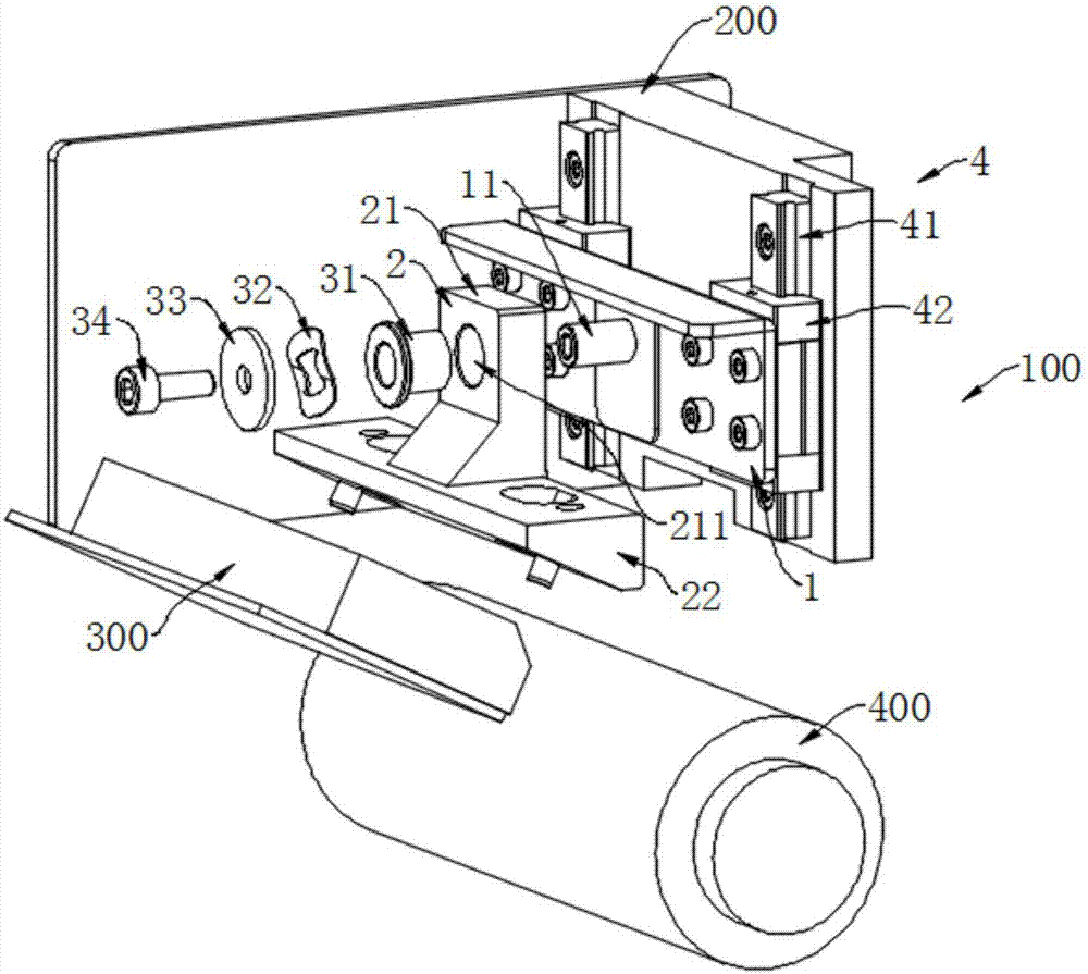
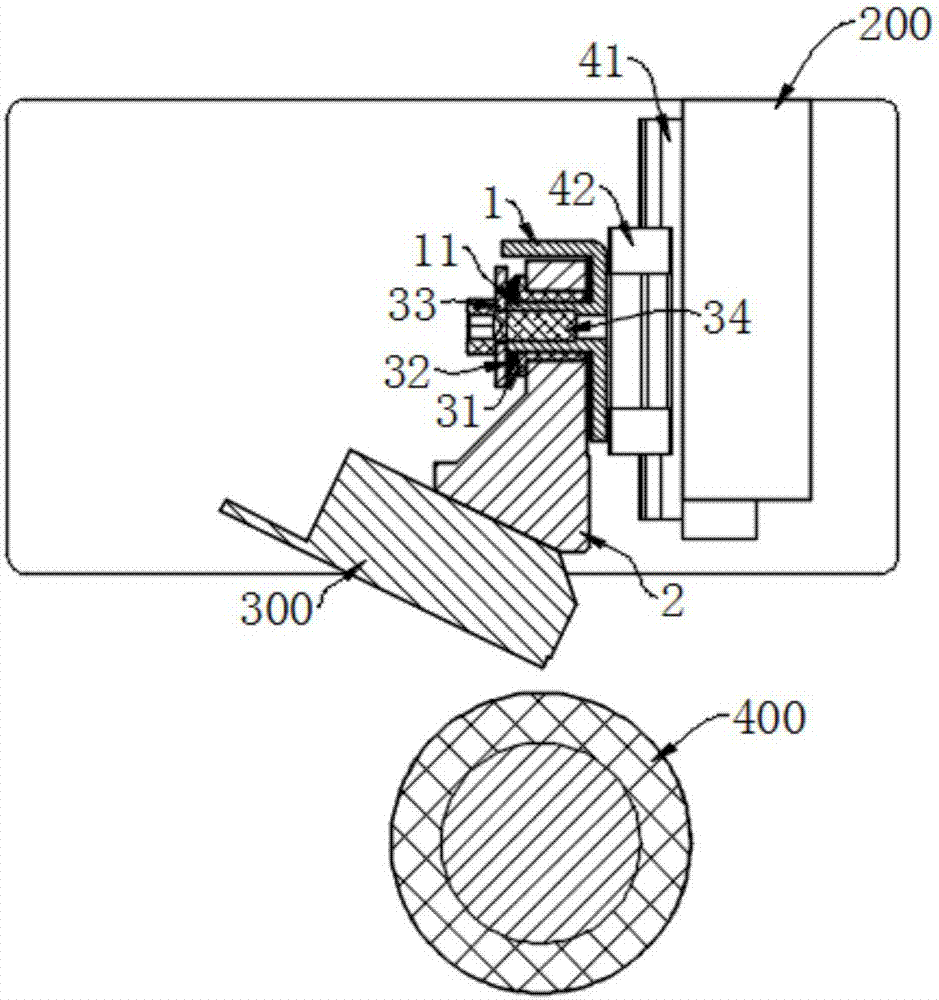
[0035] Reference Figure 1 to Figure 8 As shown, the background and concept of the present invention is: in the printing state, the print head 300 exerts a certain pressure on the rubber roller 400 so that the toner coating on the carbon belt is transferred to the recording medium. Therefore, when the print head 300 and the rubber roller 400 are arranged in parallel, the pressure of the print head 300 on the contact line with the rubber roller 400 is evenly distributed, which helps to improve the uniformity and consistency of the print marks. In the present invention, by designing the connecting assembly 3 and applying the print head 300 to apply a certain pressure to the rubber roller 400, a torque is generated in the case of unbalanced forces to make the connecting frame 2 rotate, thereby realizing adjustment. It has the advantages of automatic, adaptive, and real-time adjustment.

[0036] The adjusting device 100 includes a fixing frame 1, a connecting frame 2 and a connecting...

Embodiment 2

[0048] Reference Figure 1 to Figure 8 As shown, the printer uses the adjustment device 100 in Embodiment 1. The printer further includes a printer base 200, a print head 300, and a rubber roller 400. The adjustment device 100 is set on the printer base 200 via a fixed frame 1. Above, the print head 300 is fixed on the connecting frame 2, and in the printing state, the print head 300 and the rubber roller 400 are in line contact. The print head 300 can linearly reciprocate relative to the rubber roller 400. The recording medium passes through the gap between the print head 300 and the rubber roller 400. The print head 300 presses the carbon ribbon against the recording medium, and the toner on the carbon ribbon is heated. The coating transfer is printed on the recording medium.


PUM


Abstract

The invention provides a printing head self-adaptive adjustment device which comprises a fixing rack, a connecting rack and a connecting component; the fixing rack is arranged on a printer base; a printing head is arranged on the connecting rack; the connecting rack is connected with the fixing rack by the connecting component; the connecting rack has a locking state and a rotation adjustment state relative to the fixing rack; the connecting component comprises a connecting piece and an elastic piece; the connecting rack is connected with the fixing rack through the connecting piece; and the elastic piece generates pressure on the matching end faces of the connecting piece and the fixing rack. In a rotation adjustment state, the printing head deflects relative to a rubber roller, by this time, the pressure on the contact line of the printing head and the rubber roller is not balanced, and then torque driving the connecting rack to deflect is generated till the contact line of the printing head and the rubber roller is stressed uniformly. Self-adaptive adjustment on the parallelism degree of the printing head and the rubber roller is realized, the contact line of the printing head and the rubber roller is stressed uniformly, and thus the printing quality is improved.

Description

Technical field [0001] The present invention relates to the field of printers, and in particular to an adaptive adjustment device for a print head and its printer. Background technique [0002] At present, thermal transfer technology uses a special ribbon to transfer the toner coating on the ribbon to paper or other types of materials by heating the print head. Because the coating material on the ribbon can be Choose according to your needs, produce stronger adhesion, plus the choice of printing media, to better ensure that the printed handwriting is not affected by the outside world. The working surface of the print head on the thermal transfer printer is a straight line, and the straight line and the bottom rubber roller need to be in parallel contact to print the same clear content. When the rubber roller is relatively long, it is difficult to adjust the parallelism between the print head and the rubber roller to be completely parallel, which affects the printing effect. The...

Claims


Application Information

Patent Timeline
Patent Type & Authority Applications(China)
IPC IPC(8): B41J25/00
CPCB41J25/001
Inventor 苏建洲
Owner XIAMEN HANIN ELECTRONICS TECH CO LTD
Learn More