A Method for Realizing Unilateral Tensioning Device and Its Power Distribution Using DC Motor

A DC motor and power distribution technology, applied in the direction of brakes, etc., can solve the problems of vehicles stopping, wheels not being distributed, and personnel injuries in vehicles, etc.

Inactive Publication Date: 2019-05-14
TONGREN UNIV +1
View PDF6 Cites 0 Cited by
  • Summary
  • Abstract
  • Description
  • Claims
  • Application Information

AI Technical Summary

Problems solved by technology

[0002] With the development of science and technology and the improvement of people's living standards, cars have entered the homes of ordinary people. In daily life, driving a car to and from get off work has become the norm; The most important thing to consider, because the vehicle is equipped with a differential, the differential has the function of automatically distributing power, but when one of the wheels slips, according to the principle of the lowest energy, the engine at this time will "lazily" put it All the kinetic energy of the vehicle is distributed to the slipping wheels, causing no power to be distributed to the wheels with high friction, causing the vehicle to stop
However, when the vehicle is out of control and the personnel in the vehicle cannot manually control the work of the vehicle differential, it will cause injury to the personnel in the vehicle. Therefore, we propose a method of using a DC motor to realize the unilateral tensioning device and its power distribution

Method used


Image

  • A Method for Realizing Unilateral Tensioning Device and Its Power Distribution Using DC Motor
  • A Method for Realizing Unilateral Tensioning Device and Its Power Distribution Using DC Motor
  • A Method for Realizing Unilateral Tensioning Device and Its Power Distribution Using DC Motor

Examples


Embodiment Construction

[0020] The following will clearly and completely describe the technical solutions in the embodiments of the present invention with reference to the accompanying drawings in the embodiments of the present invention. Obviously, the described embodiments are only some, not all, embodiments of the present invention.

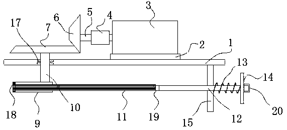
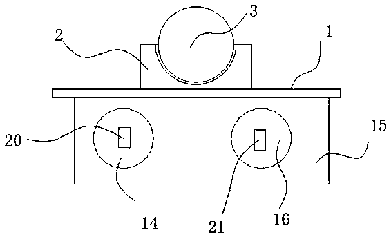
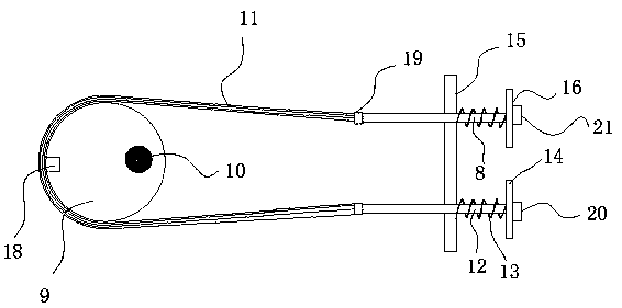
[0021] refer to Figure 1-3 , a unilateral tensioning device realized by a DC motor, comprising a fixed plate 1 and a motor 3, the motor 3 is a DC forward and reverse motor. And the motor 3 can be connected with the vehicle power supply through the control switch, and the control switch is arranged in the driver's compartment, which can realize the real-time control of the driver.

[0022] The motor 3 is connected to the fixed plate 1 through the motor base 2, the rotating shaft of the motor 3 is coaxially installed with the drive shaft 5, the drive shaft 5 is provided with a slipper 4, and the end of the slipper 4 away from the motor 3 is connected to the first cone...


PUM


Abstract

The invention discloses a device for achieving unilateral tensioning through a direct current motor. The device comprises a fixing plate and the motor. The motor is connected to the fixing plate through a motor seat, and a rotary shaft of the motor is coaxially installed on a driving shaft; a skidding device is arranged on the driving shaft, and the end, away from the motor, of the skidding device is connected with a first bevel gear through a transmission shaft; a second bevel gear is arranged on the position located in the perpendicular direction of the first bevel gear, arranged parallel to the fixing plate and engaged with the first bevel gear; and a connecting shaft is coaxially installed on the bottom surface of the second bevel gear and penetrates through the fixing plate and stretches to the position below the fixing plate, and the connecting shaft and the fixing plate are connected through a bearing. The invention further provides a power distribution method of the device for achieving unilateral tensioning through the direct current motor. According to the device for achieving unilateral tensioning through the direct current motor and the power distribution method of the device, when forward direct current or reverse direct current is connected to the motor, deflection occurs to an eccentric wheel, so that chain multiple brake cables are driven to be timely tensioned, control over a skidding wheel is achieved, and driving safety is guaranteed.

Description

technical field [0001] The invention relates to the technical field of vehicle braking devices, in particular to a method for realizing a single-side tensioning device and its power distribution by using a DC motor. Background technique [0002] With the development of science and technology and the improvement of people's living standards, cars have entered the homes of ordinary people. In daily life, driving a car to and from get off work has become the norm; The most important thing to consider, because the vehicle is equipped with a differential, the differential has the function of automatically distributing power, but when one of the wheels slips, according to the principle of the lowest energy, the engine at this time will "lazily" put it The kinetic energy of the vehicle is all distributed to the slipping wheels, resulting in no power distribution to the wheels with high friction, so that the vehicle stops. However, when the vehicle is out of control and the personnel...

Claims


Application Information

Patent Timeline
Patent Type & Authority Patents(China)
IPC IPC(8): B60T8/1761
CPCB60T8/1761
Inventor 侯天凤
Owner TONGREN UNIV
Why Eureka
Try Eureka