High-temperature film half-bridge resistance strain gauge with temperature self-compensation function and preparation method of high-temperature film half-bridge resistance strain gauge

A resistance strain gauge and half-bridge technology, applied in the field of high-temperature thin-film half-bridge resistance strain gauge and its preparation, can solve the problems of increasing technical difficulty, increasing operation steps, etc., so as to eliminate drift strain error, eliminate apparent strain error, Effect of Minimizing Transverse Strain Error

Active Publication Date: 2017-10-20
UNIV OF ELECTRONICS SCI & TECH OF CHINA
View PDF2 Cites 8 Cited by
  • Summary
  • Abstract
  • Description
  • Claims
  • Application Information

AI Technical Summary

Problems solved by technology

For example, using platinum (Pt) as a compensation material or using a material with a positive temperature coefficient (Pt) and a material with a negative temperature coefficient (ITO) to reduce the error caused by the temperature on the strain gauge; but these two This method not only needs to explore the properties of various materials, but also needs to coordinate the ratio of different materials, and carry out multiple times of patterned deposition and compounding of sensitive layers, which increases the operation steps and increases the technical difficulty.

Method used


Image

  • High-temperature film half-bridge resistance strain gauge with temperature self-compensation function and preparation method of high-temperature film half-bridge resistance strain gauge
  • High-temperature film half-bridge resistance strain gauge with temperature self-compensation function and preparation method of high-temperature film half-bridge resistance strain gauge
  • High-temperature film half-bridge resistance strain gauge with temperature self-compensation function and preparation method of high-temperature film half-bridge resistance strain gauge

Examples


Embodiment Construction

[0025] The present invention will be further described below in conjunction with the accompanying drawings and embodiments.

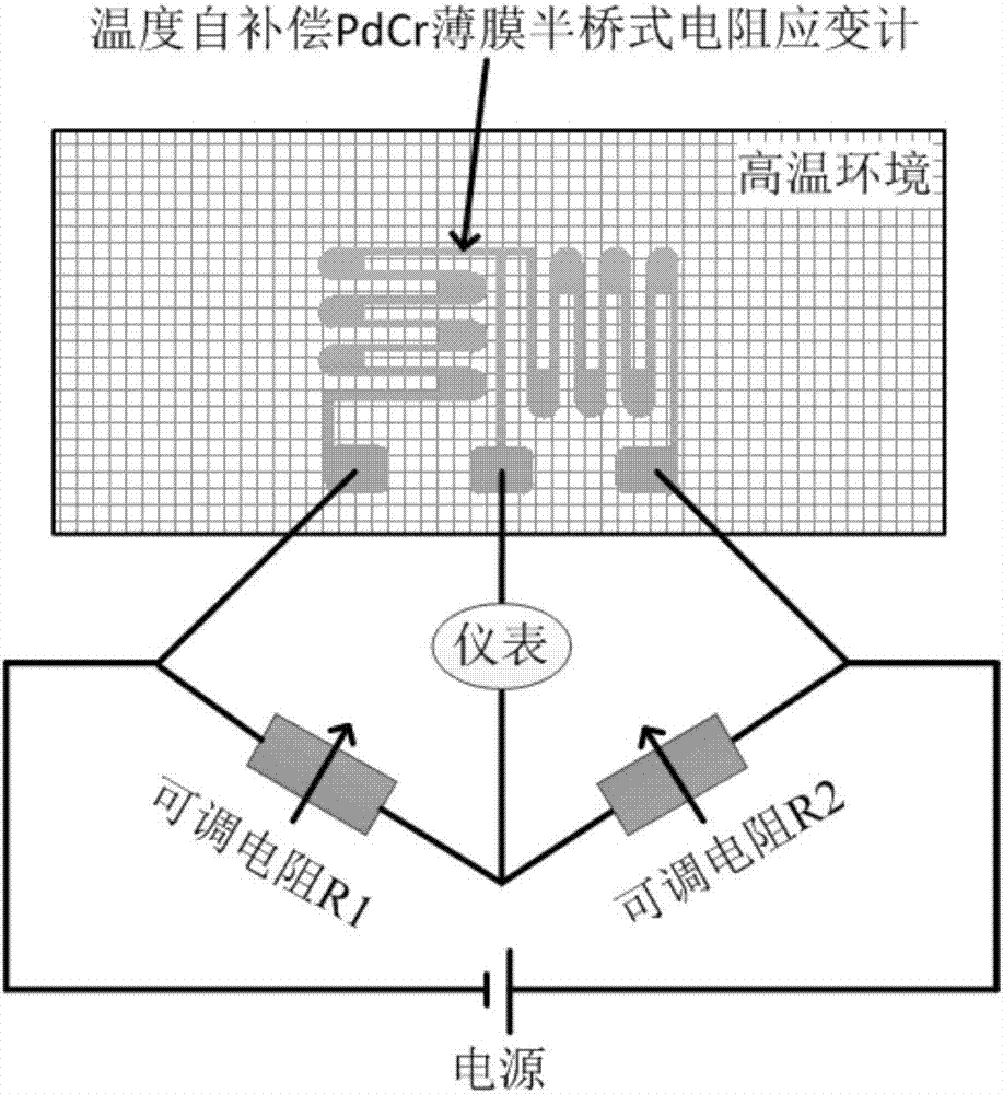
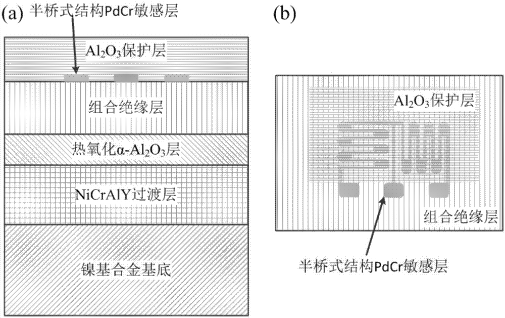
[0026] This embodiment provides a high-temperature film half-bridge resistance strain gauge with temperature self-compensation and its preparation method. The schematic diagram of the Wheatstone bridge connection mode of the strain gauge is as follows figure 1 As shown, the schematic diagram of the device structure is shown in figure 2 As shown, it includes nickel-based alloy substrate, NiCrAlY buffer layer, thermally oxidized α-Al 2 o 3 layer, YSZ / Al 2 o 3 / YSZ / Al 2 o 3 Combined insulating layer, PdCr strain-sensitive layer (functional layer) with half-bridge structure, Al 2 o 3 Protective layer; Its preparation method comprises the following steps:

[0027] Step 1: Polish the nickel-based alloy substrate whose length×width×height are 100×30×3 mm by machine or manually, and ultrasonically clean it with acetone, alcohol and deionized water;

...


PUM


Abstract

The invention belongs to the technical field of film resistance strain gauges and provides a high-temperature film half-bridge resistance strain gauge with a temperature self-compensation function and a preparation method of the high-temperature film half-bridge resistance strain gauge. The high-temperature film half-bridge resistance strain gauge is suitable for a high-temperature environment in which the in-situ temperature cannot be directly measured or the temperature is in a dynamic fluctuation state. The half-bridge resistance strain gauge comprises a nickel-based alloy substrate, a buffering layer, an insulating layer, a functional layer and a protective layer which are sequentially stacked from bottom to top; the functional layer is composed of two graphical strain sensing units with the same structure; the two graphical strain sensing units are vertical to each other to jointly form a half-bridge structure; apparent strain errors caused by temperature fluctuation (change) and drifting strain errors caused by resistance drifting of a sensing layer in a testing process can be effectively self-compensated by connecting the film half-bridge resistance strain gauge into a Wheatstone bridge circuit, so that the testing precision and accuracy of the strain gauge are improved; in addition, the high-temperature film half-bridge resistance strain gauge with the temperature self-compensation function is simple in preparation process, low in preparation cost and beneficial to industrial production.

Description

technical field [0001] The invention belongs to the technical field of thin-film resistance strain gauges, and provides a high-temperature thin-film half-bridge resistance strain gauge with temperature self-compensation and a preparation method thereof, which are suitable for high-temperature environments where in-situ temperature is not suitable for direct measurement or where the temperature is dynamically fluctuating. technical background [0002] With the general increase of the operating environment temperature, the materials of some key parts are close to their service limit temperature. For example, the temperature of the combustion chamber of the new generation of aero-engine has reached above 1500 ℃, and the turbine blades working in it will appear with the increase of service time. Cracks, falling off, causing disastrous consequences. Therefore, it is necessary to monitor the mechanical parameters such as stress and strain on the surface of the turbine blade in sit...

Claims


Application Information

Patent Timeline
Patent Type & Authority Applications(China)
IPC IPC(8): C23C14/35C23C14/16C23C14/08C23C14/18C23C14/04C23C14/58G01B7/16
CPCC23C14/0036C23C14/042C23C14/08C23C14/081C23C14/165C23C14/185C23C14/352C23C14/5806C23C14/5853G01B7/18
Inventor 蒋书文刘豪赵晓辉蒋洪川张万里
Owner UNIV OF ELECTRONICS SCI & TECH OF CHINA
Why Eureka
Try Eureka