Apparatuses for reducing angular velocity of protective shells associated with protective headwear

A headgear, angular velocity technology, used in helmets, applications, eye surgery, etc.

Pending Publication Date: 2017-10-20
ILLINOIS TOOL WORKS INC
View PDF7 Cites 0 Cited by
  • Summary
  • Abstract
  • Description
  • Claims
  • Application Information

AI Technical Summary

Problems solved by technology

[0008] One problem with tightening the nut and increasing the normal force is that while it does reduce the ang

Method used


Image

  • Apparatuses for reducing angular velocity of protective shells associated with protective headwear
  • Apparatuses for reducing angular velocity of protective shells associated with protective headwear
  • Apparatuses for reducing angular velocity of protective shells associated with protective headwear

Examples


Embodiment Construction

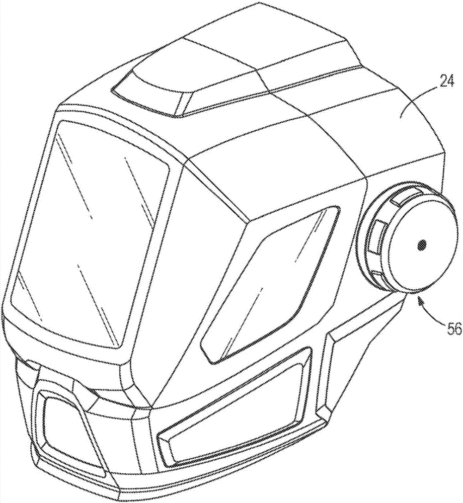
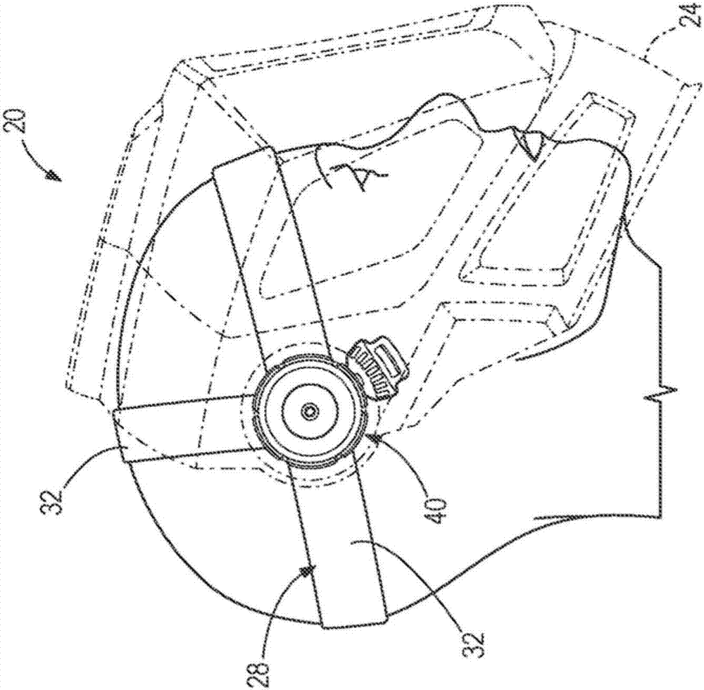
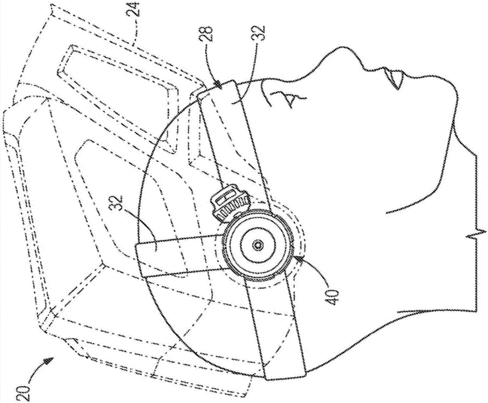
[0056] A user needs to wear the protective headgear 20 in various environments in an attempt to provide protection to the user's head. Protective headgear 20 typically has more weight than a typical baseball cap or other non-protective headgear 20, thus putting stress on the user's neck. There are many types of protective headgear 20 including, but not limited to, hard hats, welding helmets, grinding helmets, and the like. Some of the protective headgear 20 include movable parts that can apply additional stress to the user's neck. For example, during movement of the component and / or when movement of the component ceases, increased stress may be applied to the user's neck to initiate movement of the component. One example of protective headgear 20 that includes moving parts is a welding helmet 20 . For the purpose of illustrating at least some of the principles of the present disclosure, welding helmet 20 will be shown and described. However, the illustration and description...


PUM

PropertyMeasurementUnit
Verticalityaaaaaaaaaa

Abstract

A protective headwear (20) is provided and includes a support member (28) configured to engage a user's head, an outer shell (24) coupled to the support member (28) and rotatable relative to the support member (28) between a first position and a second position, and a member (52) coupled between the support member (28) and the outer shell (24) to reduce angular velocity of the outer shell (24) as it moves from the first position to the second position. The protective headwear may be a welding helmet.

Description

[0001] related application [0002] This application claims the benefit of priority to US Provisional Patent Application No. 62 / 096,948, filed December 26, 2014, which is incorporated herein by reference in its entirety. technical field [0003] The present disclosure relates generally to protective headgear, and more particularly to movement of protective headgear relative to a user's head. Background technique [0004] Several types of protective headgear exist. A welding helmet is one example of protective headgear, and some conventional welding helmets include an outer protective shell and a headgear for supporting the shell on the user's head. The housing at least partially surrounds the user's head to provide protection. [0005] A common activity that most welders perform on a daily basis is clicking their welding helmets to move the shell from an upward, non-operating position to a downward operating position. The nodding motion, which may include quick twists of ...

Claims


Application Information

Patent Timeline
IPC IPC(8): A42B3/22
CPCA42B3/225A61F9/06A42B3/222
Inventor 尼桑可·R·帕特尔艾瑞克·T·索莫斯凯尔·法埃佛
Owner ILLINOIS TOOL WORKS INC
Why Eureka
Try Eureka