Impeller, blade of the impeller, and vertical axis wind power generator using the impeller

A technology of wind power generators and vertical shafts, applied to wind power generators, wind power generators at right angles to the wind direction, motors, etc., which can solve the problems of high wind power required for start-up, high work efficiency, and low power generation efficiency, so as to improve work efficiency , reduce wind resistance, high speed effect

Inactive Publication Date: 2016-09-07
HUANGHE S & T COLLEGE
View PDF7 Cites 0 Cited by
  • Summary
  • Abstract
  • Description
  • Claims
  • Application Information

AI Technical Summary

Problems solved by technology

Among them, the main shaft of the horizontal axis wind turbine is parallel to the wind direction, and a wind deflecting tail is installed on it to adapt to the wind direction. The wind force required for starting is relatively large, and it is more easily affected by terrain and ground objects, but the work efficiency is relatively high.
The main shaft of the vertical-axis wind turbine is perpendicular to the wind direction, and the barrel-shaped impeller with S-shaped blades is mainly used. According to the working principle of the Sabinius fan, the impeller is divided into a power area and a resistance area in the airflow, relying on air resistance to perform work. , the blade includes a windward side and an upwind side. The windward side is set upwind when the blade rotates to the power area, and the upwind side is set upwind when the blade rotates to the resistance area. The force generated by the wind on the blade in the power area is greater than that in the resistance area. The principle of the force generated on the blades makes the blades rotate, and the wind required for starting is small. However, because the blades that rotate to the resistance area will produce resistance to the rotation of the blades that rotate to the power area, the rotation speed is relatively slow. Relatively low power generation efficiency

Method used


Image

  • Impeller, blade of the impeller, and vertical axis wind power generator using the impeller

Examples


Embodiment Construction

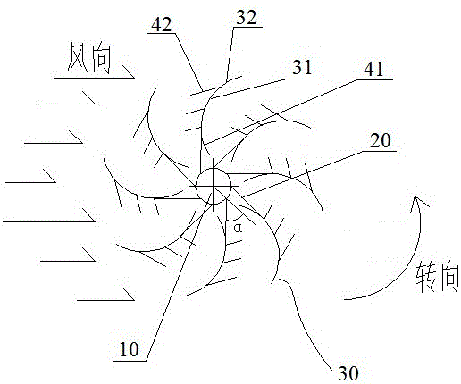
[0017] An example of an impeller in the present invention is figure 1 Shown is an impeller of a vertical axis wind power generator, including a shaft 10 and blades 30 . The blades 30 extend along the axial direction of the rotating shaft 10 and are fixed on the rotating shaft 10 through corresponding blade support rods 20 . The cross-section of each blade 30 perpendicular to the rotating shaft 10 is arc-shaped, and forms an S-shape together with the blades on the opposite side. When working, the impeller follows the figure 1 set in the way of figure 1 Rotate in the direction shown by the arc-shaped arrow, the axial direction of the rotating shaft 10 is perpendicular to the wind direction, the air flow forms a power area below the rotating shaft 10, and forms a resistance area above the rotating shaft 10.

[0018] The outer end of each blade 30 away from the center of rotation is inclined towards a side away from the rotation direction of the blade 30 , so that the blade 30 ...


PUM


Abstract

The invention relates to an impeller, a blade of the impeller and a vertical-axis wind driven generator using the impeller. The blade of the impeller is provided with a windward side facing the wind when rotating to a power area of the impeller and a leeward face facing the wind when rotating to a resistance area of the impeller, wherein a leeward guide plate is arranged on the leeward face in a mode and obliquely arranged relative to the blade so as to enable one side away from the blade to incline towards the rotation axis of the blade. The impeller comprises a rotation shaft and the blade. The vertical-axis wind driven generator comprises a machine frame and the impeller. Due to the fact that the leeward guide plate is arranged, the leeward guide plate can enable a part of fluid in the resistance area to flow into the impeller along the leeward guide plate and do work on the blade in front of the blade rotation direction so as to increase forward acting force suffered by the whole impeller when the blade rotates the resistance area of the impeller, meanwhile wind resistance suffered by the blade in the resistance area is decreased, and further the impeller can achieve high rotation speed and improve the working efficiency.

Description

technical field [0001] The invention relates to an impeller, a blade of the impeller and a vertical axis wind power generator using the impeller. Background technique [0002] Wind power generation uses wind power to drive the impeller of the generator to rotate, and then drives the unit to run to generate electricity. It has no pollution to the environment and is easy to arrange. It is a green energy source and is especially suitable for use in areas where electricity is not easily delivered. In the prior art, wind power generators can be classified into horizontal axis wind power generators and vertical axis wind power generators according to the structure of the bearing shaft. Among them, the main shaft of the horizontal axis wind turbine is parallel to the wind direction, and a wind deflector tail is installed on it to adapt to the wind direction. The wind force required for starting is relatively large, and it is more easily affected by terrain and ground objects, but t...

Claims


Application Information

Patent Timeline
Patent Type & Authority Patents(China)
IPC IPC(8): F03D3/06F03D3/04
CPCY02E10/74
Inventor 李慧何春霞台运良陈会娟谭涛
Owner HUANGHE S & T COLLEGE
Why Eureka
Try Eureka