
Turbo fan sand washing machine

A technology of sand washing machine and turbofan, which is applied in the field of sand washing machines, can solve the problems of inability to release the carbon source of sand grains, obvious odor of sand discharge, etc., and achieve the effect of eliminating energy impact and low energy consumption

Active Publication Date: 2019-04-02
CRRC CONSTR ENG CO LTD
View PDF6 Cites 0 Cited by
  • Summary
  • Abstract
  • Description
  • Claims
  • Application Information

AI Technical Summary

Problems solved by technology

The existing sand-water separator does not have the function of sand washing, which cannot release the carbon source in the sand particles, resulting in obvious odor of sand discharge

Method used


Image

  • Turbo fan sand washing machine
  • Turbo fan sand washing machine
  • Turbo fan sand washing machine

Examples


Embodiment Construction

[0015] The present invention will be further described below through the embodiments and in conjunction with the accompanying drawings.

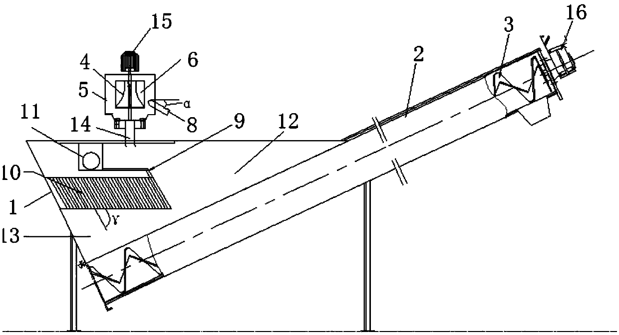
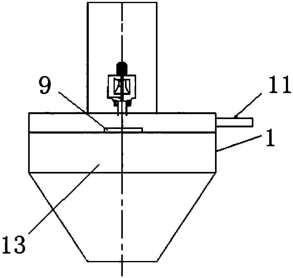
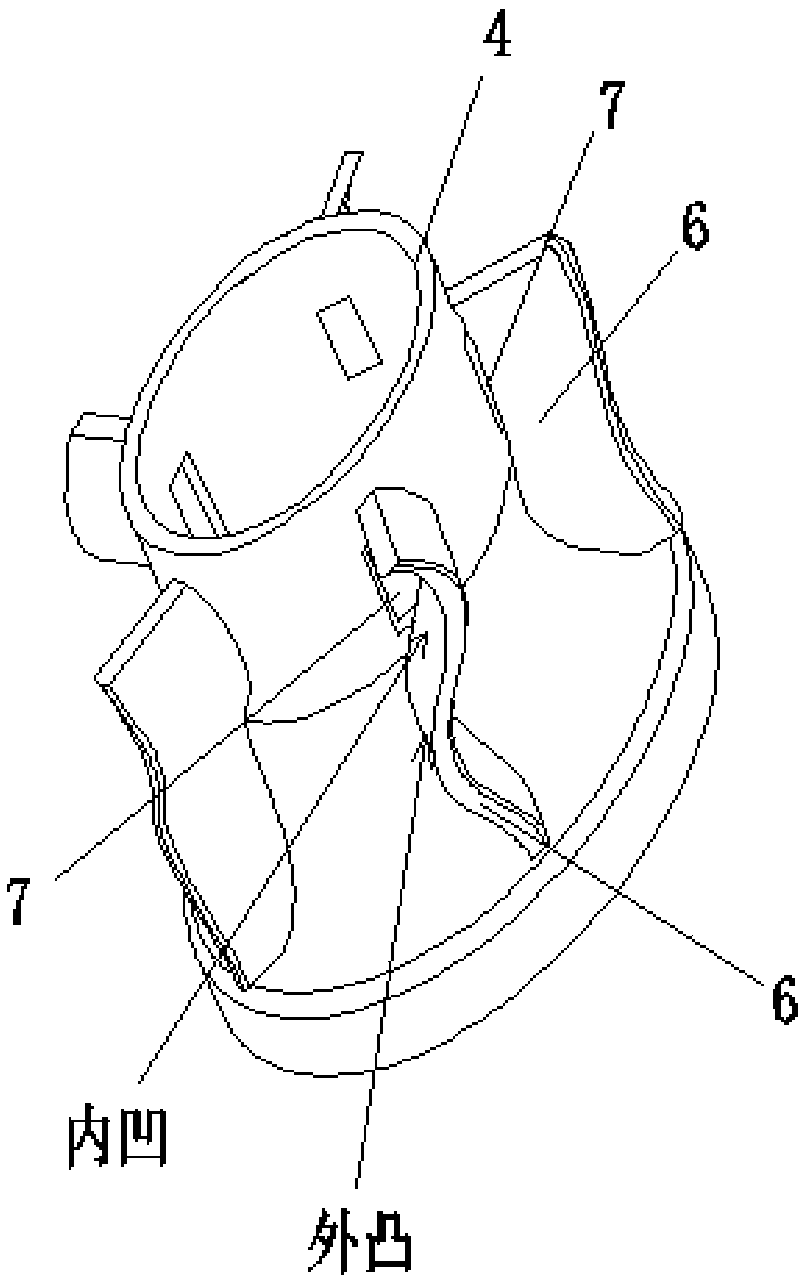
[0016] combine figure 1 — Figure 4 As shown, a turbofan sand washing machine is mainly composed of a rotating inner cylinder 4, a closed and fixed outer casing 5, and wavy paddles 6. The rotating inner cylinder 4 is located in the closed and fixed casing 5 , and bearings are installed in the closed and fixed casing 5 for realizing the relative rotation of the rotating inner cylinder 4 . The space inside the rotating inner cylinder 4 is the inner chamber, and the space between the rotating inner cylinder 4 and the closed and fixed shell 5 is the outer chamber.

[0017] The rotating inner cylinder 4 has a trumpet-shaped base. On the outer wall of the rotating inner cylinder 4, there are fixed a number of wavy paddles 6 distributed in a divergent shape. distributed.

[0018] There is a distance between the wave-shaped paddle 6 and the clo...


PUM


Abstract

The invention discloses a turbofan type sand washer. The turbofan type sand washer comprises a rotary inner cylinder and a closed and fixed outer shell. The rotary inner cylinder is provided with a horn-shaped base, the outer wall of the rotary inner cylinder is fixedly provided with a plurality of wavy blades distributed in a divergent shape, and overflow holes are formed in the upper portion of the rotary inner cylinder and located at the concave positions of the wavy blades. A tangential water inlet is formed in the side wall of the closed and fixed outer shell, the tangential water inlet right faces the convex surfaces of the wavy blades so as to directly wash the wavy blades, and a sand washing outlet is formed in the bottom of the closed and fixed outer shell. Sand and water mixtures are firstly subjected to turbofan type sand washing before entering a screw type sand-water separator, a carbon source in sand is released through a sand washing process, it is ensured that no peculiar smell is generated during sand drainage, then removal of fine sand is strengthened through flow guidance and sedimentation, and the separation effect and separation efficiency are improved.

Description

technical field [0001] The invention belongs to the technical field of sewage treatment, and in particular relates to a sand washing machine used before a sand-water separation device. Background technique [0002] The spiral sand-water separator is widely used in existing sewage plants. As a kind of sand-water separation equipment for grit chambers, it has a single structure and simple design. It is a separation and lifting equipment for sand and other solid particles in sewage. According to research, the sand-water mixture from the grit chamber contains a large amount of organic matter, and the existing sand-water separator has little contribution to the removal of organic matter on the sand surface, and the sand-water separation effect is not as good as expected. The existing sand-water separator does not have a sand washing function, which cannot release the carbon source in the sand particles, resulting in obvious odor of sand discharge. Contents of the invention [...

Claims


Application Information

Patent Timeline
Patent Type & Authority Patents(China)
IPC IPC(8): B03B7/00
CPCB03B7/00
Inventor 董志杰秦久运张立明赵志远刘亮付义临
Owner CRRC CONSTR ENG CO LTD
Learn More