Turbo fan type sand washing sand water separation device

A sand-water separation and sand-washing technology, applied in solid separation, wet separation, chemical instruments and methods, etc., can solve the problems of low efficiency, obvious sand discharge odor, poor separation effect, etc. The effect of reducing the amount of energy and eliminating the impact of energy

Active Publication Date: 2019-02-22
CRRC CONSTR ENG CO LTD
View PDF6 Cites 3 Cited by
  • Summary
  • Abstract
  • Description
  • Claims
  • Application Information

AI Technical Summary

Problems solved by technology

At the same time, the existing sand-water separator does not have the function of sand washing, the separation effect is poor, the efficiency is low, and the sand discharge has obvious odor

Method used


Image

  • Turbo fan type sand washing sand water separation device
  • Turbo fan type sand washing sand water separation device
  • Turbo fan type sand washing sand water separation device

Examples


Embodiment Construction

[0016] Below by embodiment and in conjunction with accompanying drawing, the present invention will be further described:

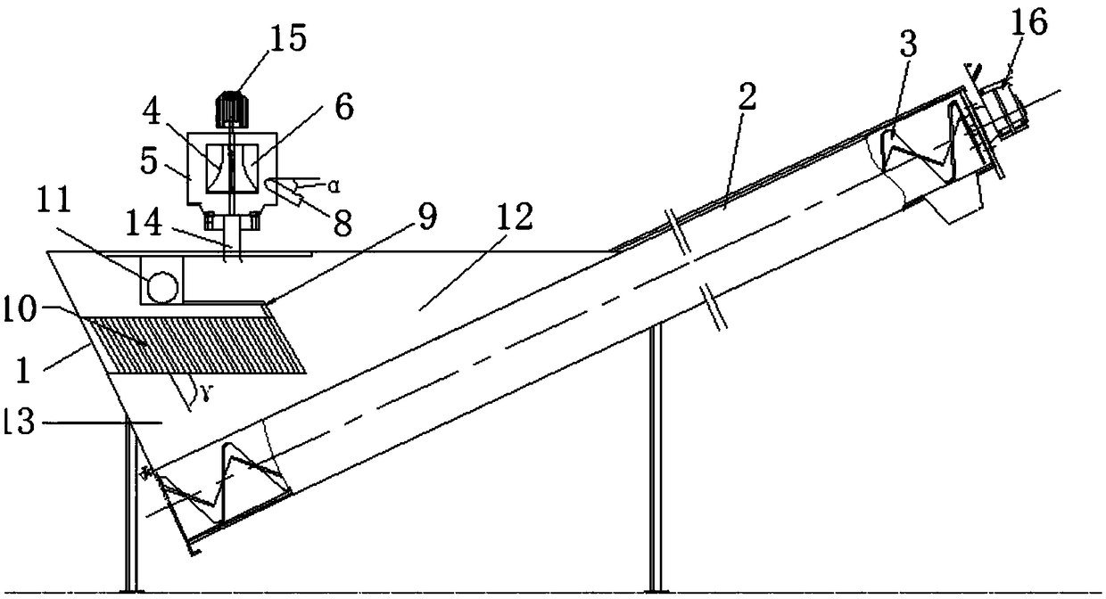
[0017] combine figure 1 — Figure 4 Shown, a turbofan type sand washing sand water separation device is mainly composed of two parts: a spiral sand water separator and a turbofan type sand washing drum.

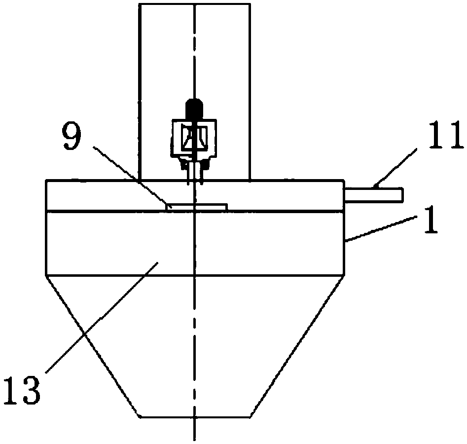
[0018] The spiral sand-water separator is mainly composed of a water collection tank 1, a U-shaped conveying tank 2, a screw conveyor 3, a flow guide 9, a settling swash plate 10, and a first motor 16.

[0019] The U-shaped conveying trough 2 is set with a low left and right high slope, the water collection tank 1 is set directly above the left end of the U-shaped conveying trough 2, the screw conveyor 3 is installed in the U-shaped conveying trough 2, and the rotation of the screw conveyor 3 is controlled by a belt reducer The drive of the first motor 16 belongs to conventional technical means. The screw conveyor 3 is preferably shaftless screw conve...


PUM


Abstract

The invention discloses a turbofan type sand-water separation device for sand washing. The turbofan type sand-water separation device comprises a screw type sand-water separator and a turbofan type sand washing drum. The screw type sand-water separator comprises a water collection tank, a U-shaped conveying groove and a spiral conveyor. The turbofan sand washing drum comprises an inner rotating cylinder and a closed fixed shell. The inner rotating cylinder is provided with a horn-shaped base, a plurality of wave-shaped paddles which are distributed in a scattered manner are fixedly arranged on the outer wall of the inner rotating cylinder, overflow holes are formed in the upper portion of the inner rotating cylinder and located in concave positions of the wave-shaped paddles, a tangential water inlet is formed in the side wall of the closed fixed shell, the tangential water inlet is right opposite to the outwards-convex surfaces of the wave-shaped paddles so that the wave-shaped paddles can be directly flushed, and a sand washing outlet is formed in the bottom of the closed fixed shell. Before entering the screw type sand-water separator, a sand-water mixture is subjected to turbofan sand washing, carbon sources in sand are released in the sand washing process, and it is ensured that no objectional odor exists in discharged sand; and then removing of fine sand is intensified through stream guidance and sedimentation, and the separation effect and the separation efficiency are improved.

Description

technical field [0001] The invention belongs to the technical field of sewage treatment, and in particular relates to a sand-water separation device with a turbofan sand washing function. Background technique [0002] The spiral sand-water separator is widely used in existing sewage plants. As a kind of sand-water separation equipment for grit chambers, it has a single structure and simple design. It is a separation and lifting equipment for sand and other solid particles in sewage. According to research, the sand-water mixture from the grit chamber contains a large amount of organic matter, and the existing sand-water separator has little contribution to the removal of organic matter on the sand surface, and the sand-water separation effect is not as good as expected. According to its characteristics, the sand-water separator can only separate sand particles with a particle size of ≥0.2mm, but in the actual operation of a sewage plant, a large amount of fine sand with a par...

Claims


Application Information

Patent Timeline
Patent Type & Authority Patents(China)
IPC IPC(8): B03B7/00
CPCB03B7/00
Inventor 董志杰吉芳英尚宪贵安健刘猛赵金波
Owner CRRC CONSTR ENG CO LTD
Why Eureka
Try Eureka