
Automatic rotating casement device and system

A technology of automatic rotation and rotation of the rod, which is applied in the direction of wing fan components, power control mechanisms, and wing fan fastening devices, and can solve the problems of single structure of public bathroom windows, low degree of automatic control of public bathroom windows, and inability to realize rotation.

Active Publication Date: 2017-10-24
唐山市欣弘食品科技有限责任公司
View PDF10 Cites 1 Cited by
  • Summary
  • Abstract
  • Description
  • Claims
  • Application Information

AI Technical Summary

Problems solved by technology

[0006] However, bathroom windows are different from ordinary windows. The main purpose of bathroom windows is to ensure the smooth flow of air in the bathroom and prevent users from feeling stuffy when taking a bath; but after investigation, it is found that the existing public bathroom windows used by primary and secondary schools have the following disadvantages: Currently The public bathroom windows used in primary and secondary schools have a single structure, either open or close, and cannot realize their own rotation; and the existing public bathroom windows have a low degree of automation control, which needs to be further improved and strengthened

Method used


Image

  • Automatic rotating casement device and system
  • Automatic rotating casement device and system
  • Automatic rotating casement device and system

Examples


Embodiment approach 1

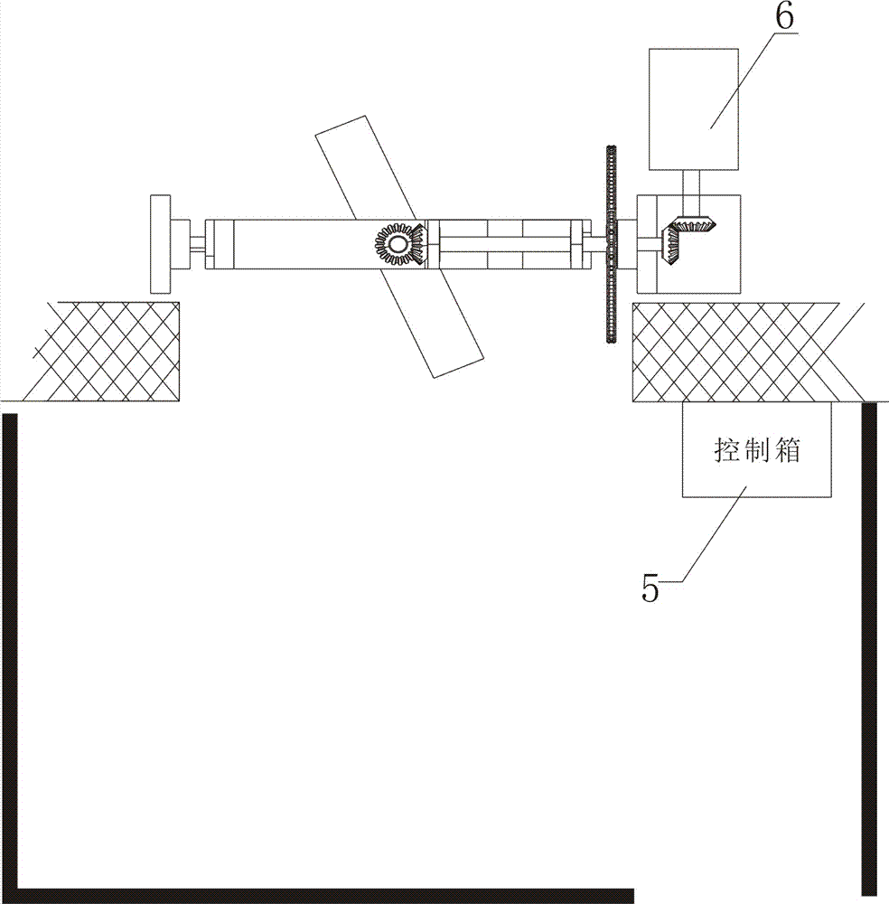
[0065] Such as Figure 5 Embodiment 1 of the bathroom automatic rotating fan system: In this embodiment, the main automatic rotating fan device in the bathroom provides power to drive the bathroom to rotate from the automatic rotating fan device;

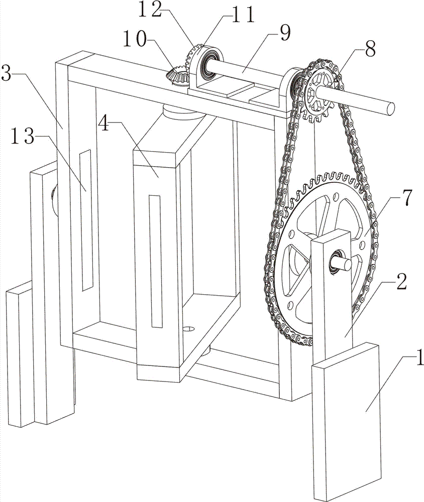
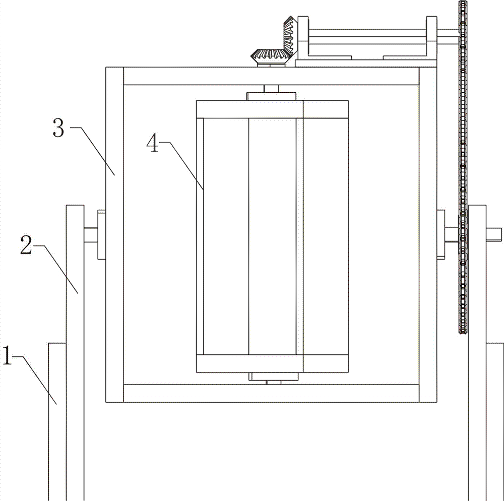
[0066] The main automatic rotating fan device in the bathroom includes a fixed base 1, a connecting seat 2, a fixed frame 3, a rotating fan 4, a control box 5, a rotating motor 6, a large rotating wheel 7, a small rotating wheel 8, and a rotating rod 9;

[0067] The fixed base 1, the connecting seat 2, and the fixed frame 3 are mutually fixed to form the main frame of the main automatic rotating fan device in the bathroom. The bevel gear A10 is set, and the large rotating wheel 7 is arranged on the connecting seat 2,

[0068] Described rotating rod 9 is arranged on the top of fixed frame 3 by two bearing blocks 11; The two ends of rotating rod 9 are all provided with bevel gear B12, and small rotating wheel 8 is fixed on the rotati...

Embodiment approach 2

[0076] Such as Figure 7 Embodiment 2 of the bathroom automatic rotating fan system;

[0077] The bathroom automatic rotating fan system, the bathroom automatic rotating fan device also includes the automatic rotating fan rotating motor 22, the large rotating wheel of the automatic rotating fan, the small rotating wheel of the automatic rotating fan; the small rotating wheel of the automatic rotating fan The wheel is fixed on the rotating rod 19 of the automatic rotating fan, and the rotating motor 22 of the automatic rotating fan is connected by a group of bevel gears and drives the large rotating wheel of the automatic rotating fan to rotate. The rotating wheels are connected by a chain; the automatic rotating fan device also has rotating power.

[0078] The difference from Embodiment 1 is that the main automatic rotating fan device in the bathroom and the automatic rotating fan device in the bathroom have rotating motors respectively, that is, each part can provide power t...


PUM


Abstract

The invention discloses an automatic rotating casement device and system for a bathroom. After improvement, the automatic rotating casement device for the bathroom comprises fixing bases, connecting seats, a fixing frame, a rotating casement, a control box, a rotating motor, a large rotating wheel, a small rotating wheel and a rotating rod. As shown in Fig.1 and Fig.2, the automatic rotating casement device for the bathroom comprises relatively few integral components, so that the structure of the device is relatively simple; during implementation, the control box is electrically connected with the rotating motor and controls the rotating motor to rotate, so that the rotating casement is driven to rotate inside the fixing frame; different from an existing bathroom window, the device can realize slow rotation of the rotating casement on the fixing frame; and the rotating casement can be a glass casement or a screen window, the air flow degree in the bathroom can be reduced through slow rotation of the rotating casement on the fixing frame during bathing, and thus the phenomena such as dizziness and the like of a person taking a bath due to closeness can be prevented.

Description

technical field [0001] The invention relates to the field of bathroom rotating fans, in particular to an automatic rotating fan device and system. Background technique [0002] At present, for primary and secondary schools, public bathrooms are used to provide students with a bathing function; however, public bathrooms are relatively airtight, in order to relieve the stuffiness during bathing and to achieve the purpose of unimpeded ventilation, so bathrooms are usually installed with various windows . [0003] After searching, it is found that the invention of patent No. CN201510100758.7 discloses an intelligent bathroom shutter, including a shutter body and a gas monitoring device; Mechanism, display screen, sound and light alarm and power module; gas concentration sensor, shutter angle sensor, electric control mechanism for shutter blade angle, display screen, sound and light alarm and power module are all connected to MCU; shutter blade angle electric control mechanism i...

Claims


Application Information

Patent Timeline
IPC IPC(8): E05F15/608E05C19/16
CPCE05C19/166E05F15/608
Inventor 朱明德张磊李建军
Owner 唐山市欣弘食品科技有限责任公司
Learn More