Pump and hydraulic power assembly using same

A hydraulic power and assembly technology, applied in the direction of liquid fuel engines, pumps, pump components, etc., can solve the problems of increasing the starting load of the motor, the large starting load, and the large motor loss, and achieve the effect of reducing the starting load and reducing the resistance.

Inactive Publication Date: 2017-10-24
HENAN MECHANICAL & ELECTRICAL VOCATIONAL COLLEGE
View PDF5 Cites 5 Cited by
  • Summary
  • Abstract
  • Description
  • Claims
  • Application Information

AI Technical Summary

Problems solved by technology

The existing problem of this kind of pump is: the rotor is driven by the motor to rotate, corresponding to the motor, the start-up load is large, not only the power consumption but also the loss of the motor is large, and in the prior art, when the motor is started, the low pressure cavity The motor is already filled with hydraulic oil, and the start of the motor can only be completed by working on the hydraulic oil, which increases the starting load of the motor, which not only leads to an increase in the minimum power when the motor is selected, but also affects the normal energy consumption of the motor

Method used


Image

  • Pump and hydraulic power assembly using same
  • Pump and hydraulic power assembly using same
  • Pump and hydraulic power assembly using same

Examples


Embodiment Construction

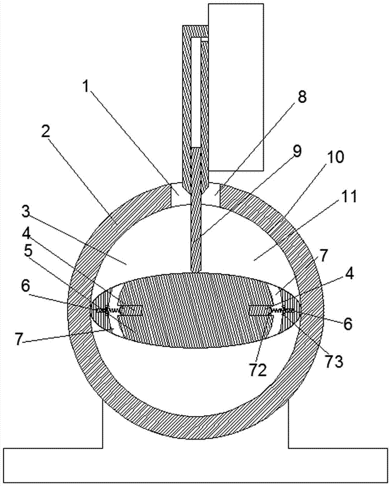
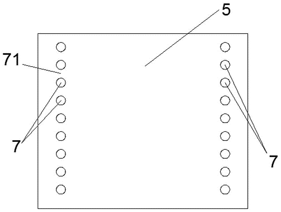
[0021] Examples of hydraulic powertrains in the present invention are Figure 1~9 Shown: includes motor 37 and pump 36, and pump 36 comprises the pump body 2 that has cylindrical hole inner chamber, is provided with the rotor 5 that rotation axis extends along the front-back direction, and cross-section is ellipse in the pump body 2, and the rotor 5 There are two tangent points between the cross section and the cylindrical inner hole. There is a hole on the pump body, and the guiding movement assembly at the hole has one end that slides and pushes with the outer peripheral surface of the rotor to separate the hole into a liquid inlet 8 and a liquid outlet. The partition 9 of 1, the inner cavity of the cylindrical hole is also separated by the partition 9 into a low-pressure chamber 11 communicating with the liquid inlet 8 and a high-pressure chamber 3 communicating with the liquid outlet 1, and the two ends of the rotor in the long diameter direction are provided with communica...


PUM


Abstract

The invention relates to a pump and a hydraulic power assembly using same. The pump comprises a pump body in which a cylindrical inner cavity is formed. A rotor of which the rotation axis extends back and forth and the cross section is elliptoid is arranged in the pump body. The two ends in the major axis direction of the rotor are provided with oil guide channels for being communicated with the two sides in the circumferential direction of the rotor. The longitudinal sections of the oil guide channels are of arc-shaped structures. The circle centers of the arc-shaped structures are located between the oil guide channels at the two sides. A plugging block is arranged in the rotor in the major axis direction in a director motion mode and has a first position and a second position in the shift motion of the plugging block; the plugging block avoids the oil guide channels at the first position; under the impact of centrifugal force, the plugging block moves outwards to block the oil guide channels at the second position. A spring which applies acting force to the plugging block to force the plugging block to be located at the first position is arranged on the rotor. The invention provides the pump capable of reducing the starting load and the hydraulic power assembly using the same.

Description

technical field [0001] The invention relates to a pump and a hydraulic power assembly using the pump. Background technique [0002] At present, hydraulic powertrains are relatively common in production and life. The hydraulic powertrain includes a motor and a pump driven by the motor. The existing pump is such as the "pump" disclosed in Chinese patent CN101749228A. A pump body is provided, and the pump body has a cylindrical hole inner cavity. A rotor whose rotation axis extends along the front and rear directions is arranged in the cylindrical hole inner cavity. There are two tangent points between the cross section of the rotor and the cylindrical hole inner cavity. There is a hole on the outer periphery of the pump body, and a baffle is installed at the hole to guide and move. The baffle divides the hole into a liquid inlet and a liquid outlet. The rotor is a cylinder. [0003] When in use, the rotor rotates clockwise, and the cavities on both sides of the rotor communic...

Claims


Application Information

Patent Timeline
Patent Type & Authority Applications(China)
IPC IPC(8): F04C2/356F04C15/00
CPCF04C2/3566F04C15/00
Inventor 马来勋
Owner HENAN MECHANICAL & ELECTRICAL VOCATIONAL COLLEGE
Why Eureka
Try Eureka