Manufacturing method of novel vacuum heat preservation container and manufactured vacuum heat preservation container thereof

A vacuum insulation and container manufacturing technology, which is applied in the direction of insulation containers, containers, non-pressure containers, etc., can solve the problems of lower insulation quality, easy drop of glass glue, heavy air, etc., and achieve the effect of improving insulation quality and ensuring insulation effect

Inactive Publication Date: 2017-10-27
FOSHAN KEITH TITANIUM TECH CO LTD
View PDF6 Cites 8 Cited by
  • Summary
  • Abstract
  • Description
  • Claims
  • Application Information

AI Technical Summary

Problems solved by technology

Because the container main body 1 is placed upside down, the air in the vacuum state is relatively heavy, so under the action of gravity, some residual air remains on the top of the heat preservation cavity 13 of the container main body 1, and complete vacuum cannot be achieved, and the heat preservation quality is reduced
In addition, the container body 1 is a metal material, and the glass glue is a non-metallic material, so the degree of fusion and the degree of adhesion between the glass glue and the container body 1 are not good, and the glass glue is bonded to the outer surface of the container body 1, and the glass glue The direction of gravity of the glue is opposite to the direction of its cohesive force with the container main body 1, so the glass glue is easy to fall off after a long time of use, and the air enters the heat preservation cavity 13 through the vent hole 31, causing the vacuum heat preservation container to lose its heat preservation effect

Method used


Image

  • Manufacturing method of novel vacuum heat preservation container and manufactured vacuum heat preservation container thereof
  • Manufacturing method of novel vacuum heat preservation container and manufactured vacuum heat preservation container thereof
  • Manufacturing method of novel vacuum heat preservation container and manufactured vacuum heat preservation container thereof

Examples


Embodiment Construction

[0034] The technical solutions of the present invention will be further described below in conjunction with the drawings and specific implementations.

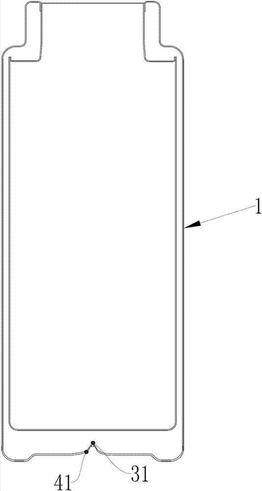
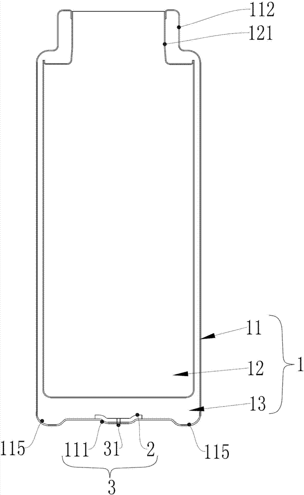
[0035] The manufacturing method of the novel vacuum insulated container of this embodiment, such as figure 2 As shown, including the following steps:

[0036] Step A, protruding the bottom of the housing 11 from inside to outside to form an exhaust groove 111;

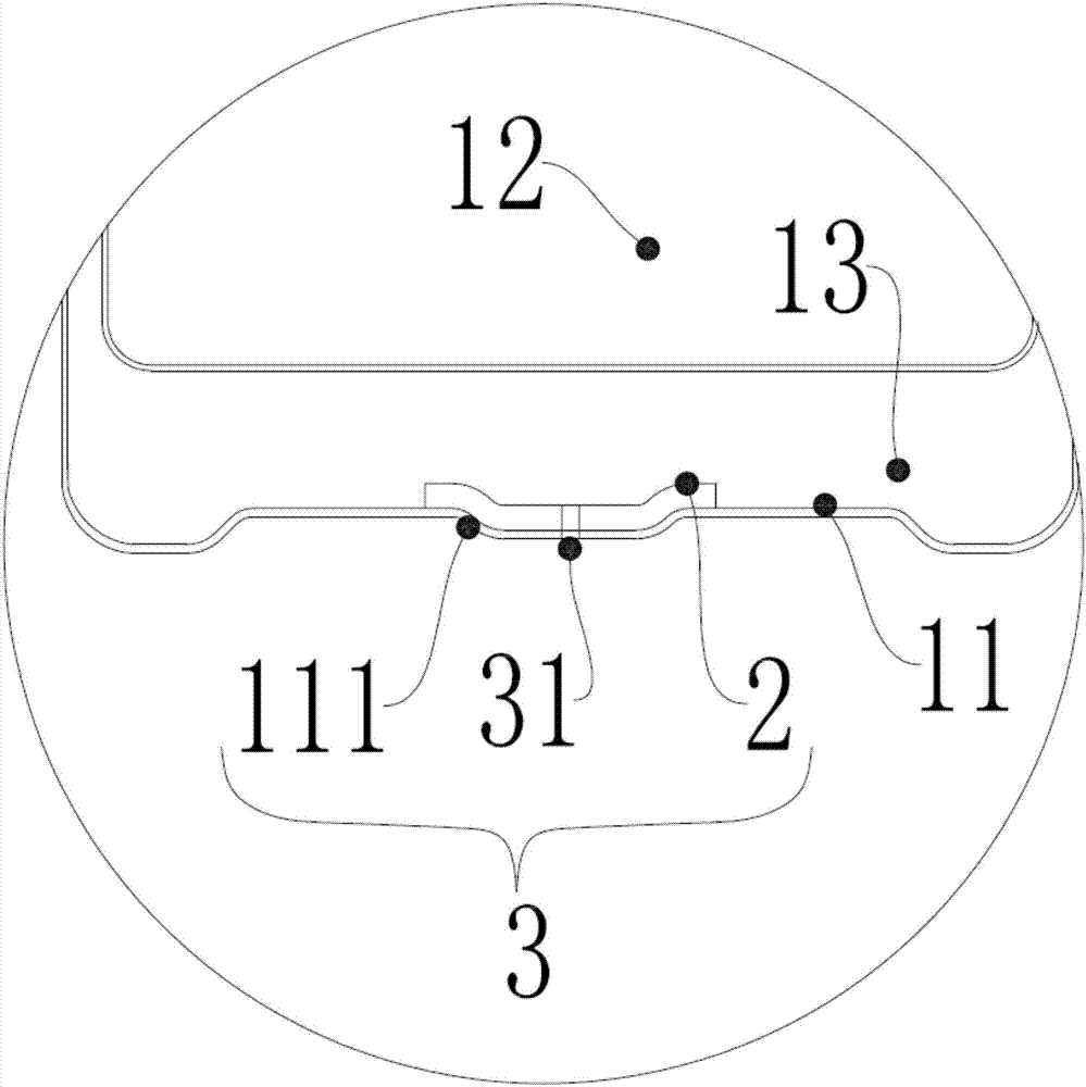
[0037] Step B, such as image 3 As shown, the low-temperature sealing layer 2 is welded to the inner wall of the exhaust groove 111, so that the exhaust groove 111 and the low-temperature sealing layer 2 form a composite layer 3;

[0038] Step C, vent holes 31 are provided in the composite layer 3;

[0039] Step D: Install the inner shell 12 in the outer shell 11 to form a container body 1. The container body 1 forms a heat preservation cavity 13 between the outer shell 11 and the inner shell 12, and the low-temperature sealing layer 2 is arranged on the heat preservation chamb...


PUM


Abstract

The invention discloses a manufacturing method of a novel vacuum heat preservation container and the manufactured vacuum heat preservation container thereof. The method includes the steps that firstly, the bottom of an outer shell protrudes from inside to outside to form a venting groove; secondly, a low-temperature sealing layer is welded to the inner wall of the venting groove, so that the venting groove and the low-temperature sealing layer are combined to constitute a composite layer; thirdly, a venting hole is formed in the composite layer. The venting hole is blocked by the low-temperature sealing layer from the interior of a container body, and the container body can be vacuumized when the container body is put straight, so that the air inside a heat preservation cavity can be completely exhausted to obtain an entirely vacuum heat preservation cavity, and the heat preservation quality is improved; moreover, the low-temperature sealing layer is welded to the interior of the outer shell, the gravity direction of the low-temperature sealing layer is same with the direction of adhesion stress of the outer shell, and the outer shell takes a supporting effect on the low-temperature sealing layer; therefore, the low-temperature sealing layer is unlikely to fall after being used for a long time, the air can be effectively prevented from entering the heat preservation cavity through the venting hole, and the heat preservation effect of the vacuum heat preservation container is ensured.

Description

Technical field [0001] The invention relates to the field of vacuum heat-preserving containers, in particular to a novel vacuum heat-preserving container manufacturing method and the vacuum heat-preserving container manufactured therefrom. Background technique [0002] The existing method for manufacturing a tailless vacuum insulated container is to dent the bottom of the container body 1 from the outside to the inside to form a protrusion 41 on its inner surface, such as figure 1 As shown, the protrusion 41 is provided with an exhaust hole 31; when vacuuming, the container body 1 needs to be placed upside down, that is, the bottom of the container body 1 faces upwards, and a solid glass glue is set on the exhaust hole 31 to exceed the melting point of the glass glue. Vacuuming is performed in a high-temperature environment such that the glass glue is melted while being vacuumed and the vent hole 31 is blocked on the outer surface of the container body 1, and then cooled to normal...

Claims


Application Information

Patent Timeline
Patent Type & Authority Applications(China)
IPC IPC(8): A47J41/02B65D81/38
CPCA47J41/022A47J41/028B65D81/3818B65D81/3869
Inventor 刘敏业
Owner FOSHAN KEITH TITANIUM TECH CO LTD
Why Eureka
Try Eureka