Magnetic attraction type glass cleaner

A cleaner and magnetic suction technology, applied in the field of glass wipes, can solve the problems of no self-cleaning ability, harsh noise, and laborious scrubbing, so as to avoid the trouble of changing water, reduce sliding resistance, and ensure the effect of scrubbing

Inactive Publication Date: 2012-01-18
涂超群
View PDF8 Cites 15 Cited by
  • Summary
  • Abstract
  • Description
  • Claims
  • Application Information

AI Technical Summary

Problems solved by technology

[0003] ① There is no self-cleaning ability, and it cannot be cleaned while wiping. It is necessary to remove the glass wiper and clean the working surface separately;
[0004] ②The glass with special structure such as arc cannot be scrubbed or the scrubbing effect is not good, and the external wiper is easy to fall off if it turns too sharply or passes through the curved surface during the scrubbing process;
[0005] ③In order to prevent the outer wiper from falling due to insufficient magnetic force when scrubbing thick glass, the traditional magnetic suction glass wiper is equipped with a magnetic body with greater magnetism, but when using this kind of glass scrubber to scrub thinner glass, it will If it is too large, the sliding resistance will be large, that is, it will be difficult for the glass wiper to move, and it will not only be laborious but also produce harsh noise when scrubbing
In order to solve this problem, some magnetic glass wipers use different types of inner and outer wipers to adapt to different thicknesses of glass, but this increases the manufacturing cost;
[0006] ④The magnetic body of the traditional magnetic glass wiper is large in volume and heavy in quality;
[0007] ⑤ Unreasonable setting of the glass wiper structure, the effective working area of ​​the glass wiper is small, and the wiping stroke is long and the efficiency is low when wiping a large area of ​​glass;
[0008] ⑥It is inconvenient to scrub the glass at a high place, and tools such as stools are needed when wiping the glass at a high place

Method used


Image

  • Magnetic attraction type glass cleaner
  • Magnetic attraction type glass cleaner
  • Magnetic attraction type glass cleaner

Examples


Embodiment 1

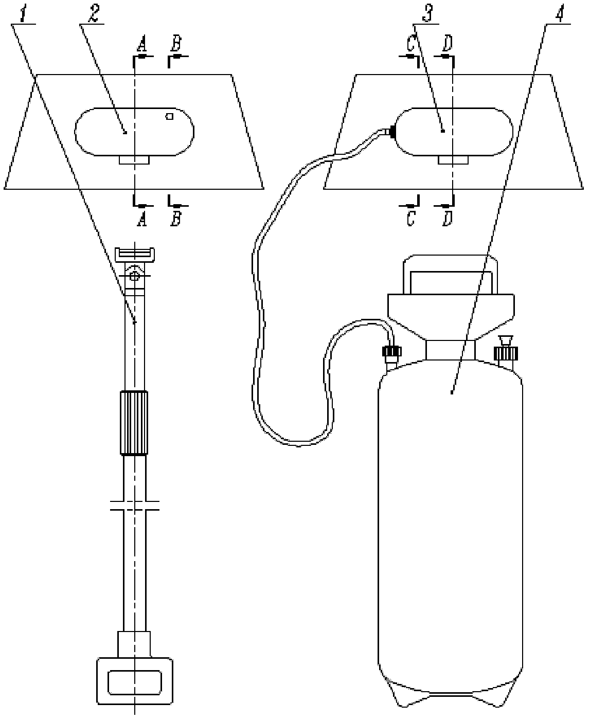
[0050] A magnetic suction type glass cleaner. Its structure and parts in use such as figure 1 Shown: including extension rod 1, inner wiper 2, outer wiper 3 and manual spray barrel 4, the water outlet of manual spray barrel 4 is connected with outer wiper 3 through a hose.

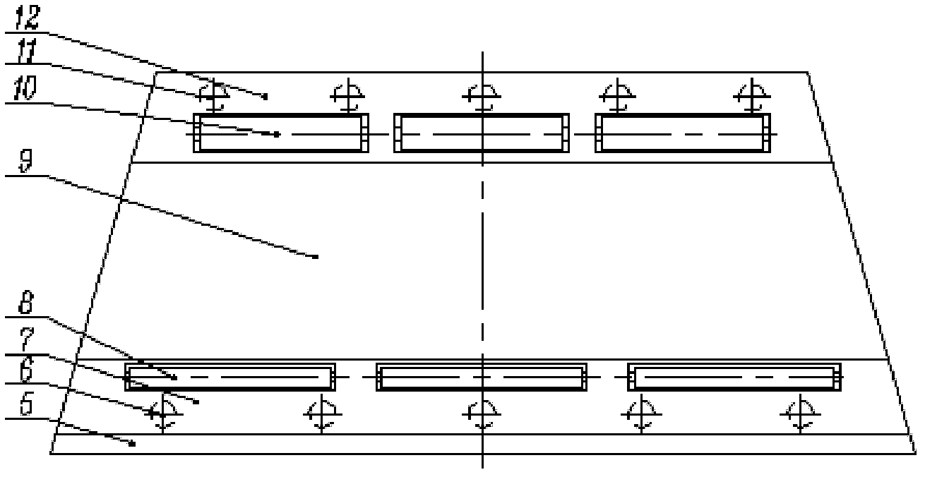
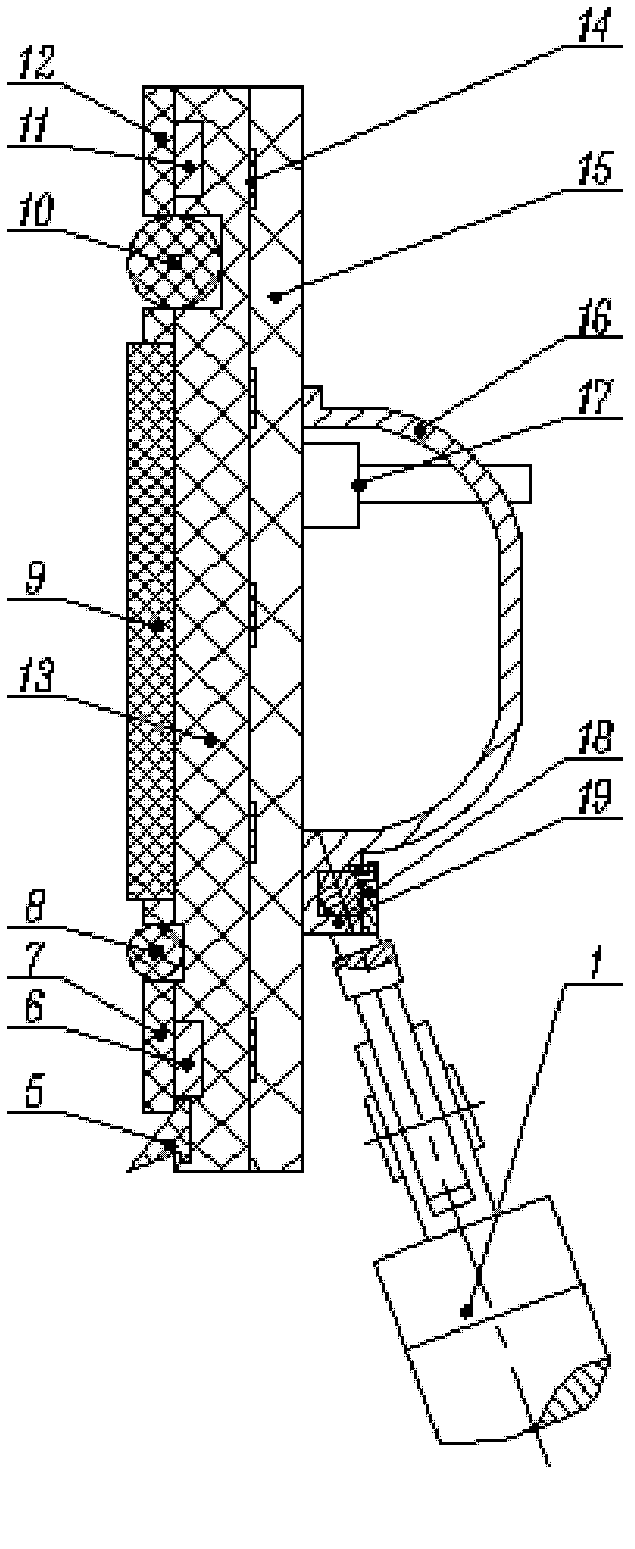
[0051] The structure of the internal friction body 2 is: the external shape of the internal friction body intermediate layer 13 and the internal friction body 15 is as follows: figure 2 As shown, all are trapezoids, let the short side of the trapezoid be up, and the long side of the trapezoid be down, figure 2 The left side of is the left side of the trapezoid, figure 2 The right side of is the right side of the trapezoid. The inner surface of the inner friction body intermediate layer 13 is bonded with the inner surface of the inner friction outer layer 15, and the inner surface of the inner friction outer layer 15 is evenly embedded with five inner friction body elastic steel strips 14.

[0052] S...

Embodiment 2

[0075] A magnetic suction type glass cleaner. The inner surface of the inner friction body intermediate layer 13 or the inner surface of the inner friction outer layer 15 are not embedded with inner friction body elastic steel bars 14, and the inner surface of the outer friction body intermediate layer 36 or the inner surface of the outer friction outer layer 38 are not embedded. Embedded with outer friction body elastic steel bar 37.

[0076] 3-4 first magnetic bodies 11 are embedded on the outer surface of the inner wiper middle layer 13 top, and 3-4 first magnetic bodies 11 are evenly distributed on the same straight line, and the first magnetic body 11 and the inner wiper wipe Two first rollers 10 are embedded on the outer surface of the inner friction body intermediate layer 13 between the cloths 9, and the two first rollers 10 are evenly installed on the same straight line.

[0077] The first fixing plate 12 is provided with two first rectangular holes, and the position...

Embodiment 3

[0089] A magnetic suction type glass cleaner. 6-10 first magnetic bodies 11 are embedded on the outer surface of the inner friction body middle layer 13 top, and 6-10 first magnetic bodies 11 are evenly distributed on the same straight line. 4-10 first rollers 10 are embedded on the outer surface of the inner wiper middle layer 13 between the cloths 9, and the 4-10 first rollers 10 are evenly installed on the same straight line.

[0090] The first fixing plate 12 is provided with 4 to 10 first rectangular holes, and the 4 to 10 first rectangular holes are respectively connected with the 4 to 10 first rollers 10 at the position of the first fixing plate 12 on the inner friction body middle layer 13. in the same position.

[0091] 6-10 second magnetic bodies 6 are embedded on the outer surface of the inner-wiping body intermediate layer 13 close to the inner-wiping body scraper 5, and 6-10 second magnetic bodies 6 are evenly distributed on the same straight line; 4-10 second r...


PUM


Abstract

The invention relates to a magnetic attraction type glass cleaner. According to the technical scheme of the invention, a glass wiper comprises an lengthening rod (1), an internal wiper body (2), an external wiper body (3) and a manual spraying barrel (4), wherein an water outlet of the manual spraying barrel (4) is connected with the external wiper body (3) through a flexible pipe. An external side face of an internal wiper body interlayer (13) is provided with 3-10 first magnetic substances (6), 2-10 first rollers (10), internal wiper body wiping cloth (9), 2-10 second rollers (8), 3-10 second magnetic substances (6) and an internal wiper body scraping plate (5) in sequence from top to bottom; the external side face of an external wiper body interlayer (36) is provided with 3-10 third magnetic substances (34), 2-10 third rollers (33), a strip-shaped groove (30), external wiper body wiping cloth (29), a fourth roller (28), a fourth magnetic substance (26) and an external wiper body scraping plate (25) in sequence from top to bottom, wherein the trip-shaped groove (30) is provided with a spraying control device (32) and 1-7 atomizing nozzles (31). The magnetic attraction type glasscleaner is convenient to use, and the wiper bodies cannot drop easily; and the magnetic attraction type glass cleaner has excellent scrubbing effect, and is suitable for scrubbing glass with different cambered surfaces.

Description

technical field [0001] The invention belongs to the technical field of glass wipes. Specifically relates to a magnetic suction type glass cleaner. Background technique [0002] With the gradual increase of high-rise buildings, and the gradual increase of windows with large sizes and special shapes such as curved surfaces, the scrubbing of high-rise glass is becoming increasingly difficult, and dangers are prone to occur during the process of scrubbing the glass. The scrubbing process is time-consuming and laborious. Difficult to guarantee. The main shortcoming that existing glass wiper exists has: [0003] ① There is no self-cleaning ability, and it cannot be cleaned while wiping. It is necessary to remove the glass wiper and clean the working surface separately; [0004] ② It is impossible to scrub glass with special structures such as arcs or the scrubbing effect is not good, and the external scrubbing body is easy to fall off when turning too sharply or passing the cur...

Claims


Application Information

Patent Timeline
Patent Type & Authority Applications(China)
IPC IPC(8): A47L1/13
Inventor 涂超群
Owner 涂超群
Why Eureka
Try Eureka