Bump bonding unit with tray storage and transport apparatuses

a technology of transport apparatus and trays, which is applied in the direction of stacking articles, de-stacking articles, manufacturing tools, etc., can solve the problem of inability to separate the trays from each other

Inactive Publication Date: 2003-11-18
PANASONIC CORP
View PDF7 Cites 14 Cited by
  • Summary
  • Abstract
  • Description
  • Claims
  • Application Information

AI Technical Summary

Benefits of technology

An object of the present invention is to provide a tray storing and feeding apparatus which is capable of certainly separating and feeding trays irr

Problems solved by technology

In particular, trays of small type form a very small or almost no space between them when piled upon one another, and in such a case it is impossible to separate the trays from each other.
I

Method used


Image

  • Bump bonding unit with tray storage and transport apparatuses
  • Bump bonding unit with tray storage and transport apparatuses
  • Bump bonding unit with tray storage and transport apparatuses

Examples


Embodiment Construction

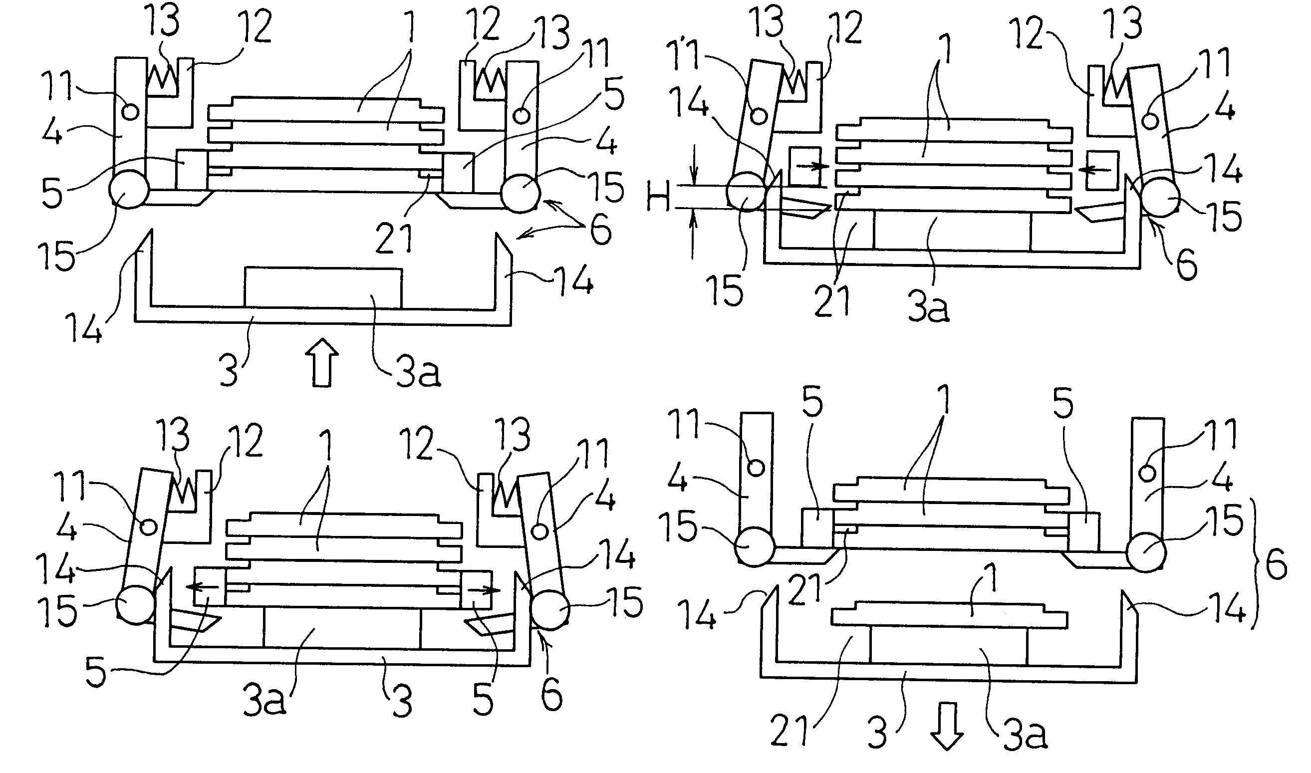
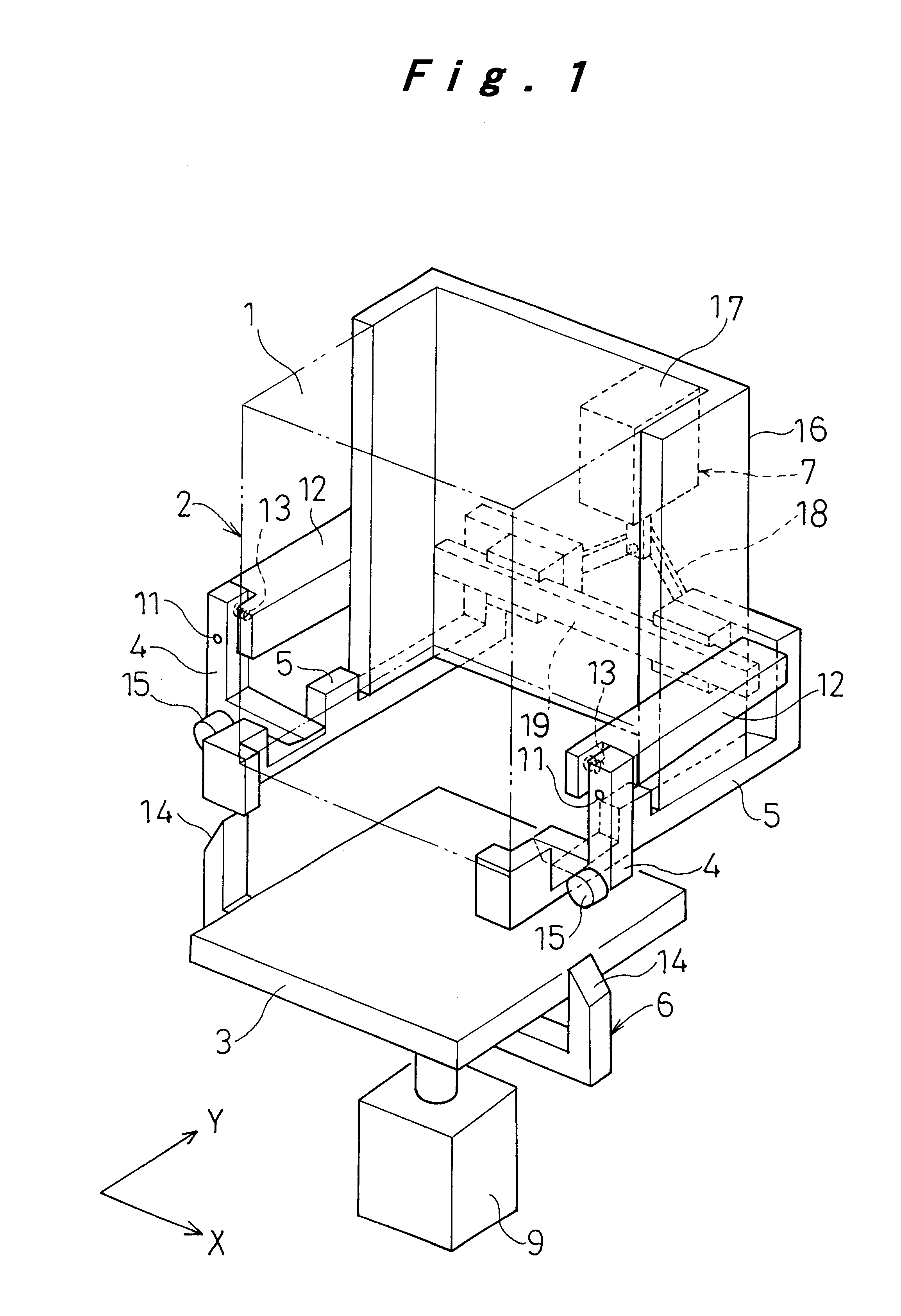
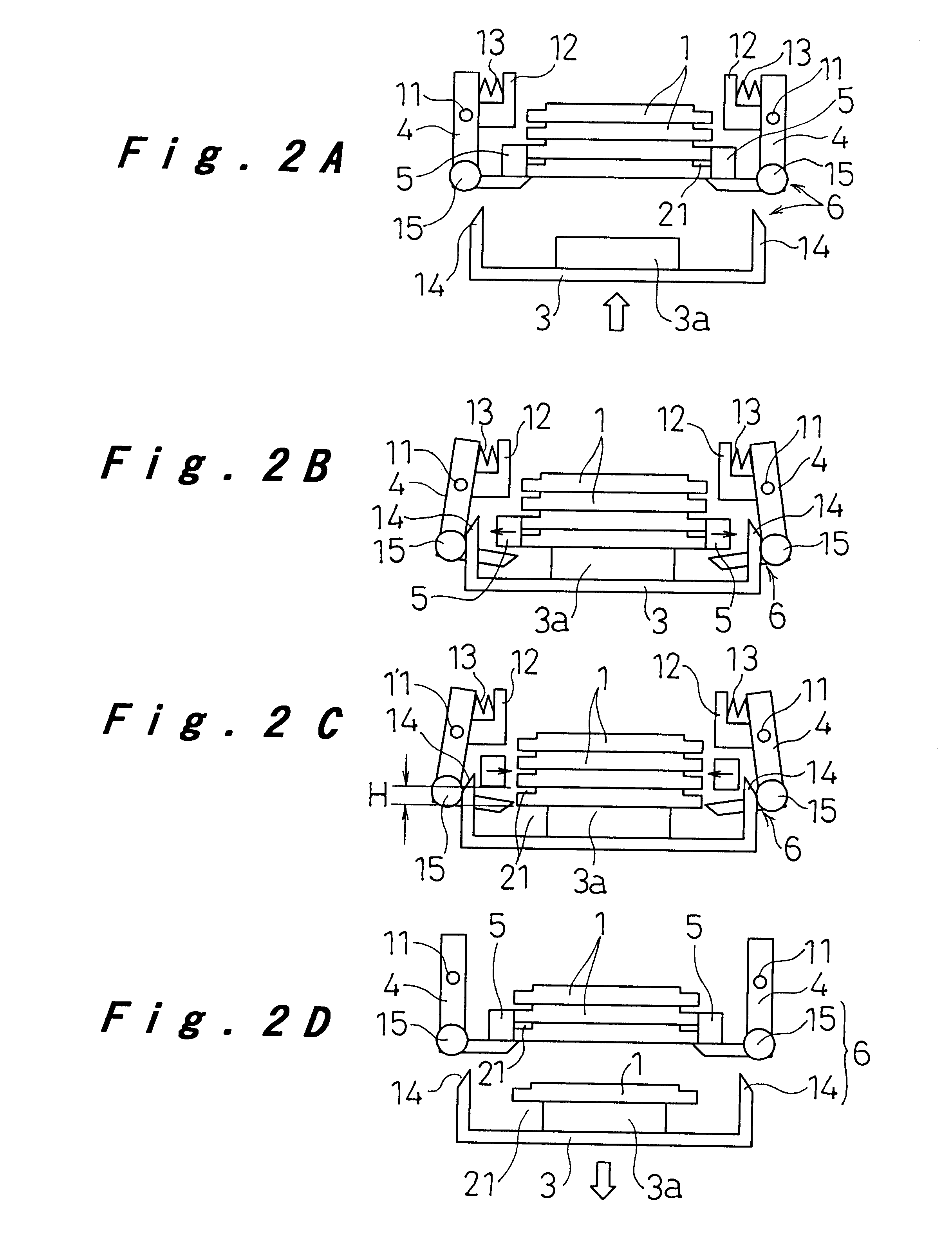
Preferred embodiments of the present invention will be hereinafter described referring to FIG. 1 to FIG. 3.

The present invention shown in the figures are embodied as a tray storing and feeding apparatus which accommodates trays accumulated one upon another on which electronic components are loaded, and is used for feeding these stored trays to a position where the components are supplied for use. The present invention is, however, not limited to such type of apparatus, and may be applied to the handling of any kind of trays.

The tray storing and feeding apparatus of the present invention includes a tray carrier 3 as shown in FIG. 1, for storing the tray 1 in a tray storage section 2 such as to be piled upon one another, as well as for feeding the tray 1 one by one to a prescribed location from the stack of trays in the tray storage section 2. The tray carrier 3 is capable of moving vertically in the tray storage section 2, and of transferring the tray 1 at its lowered position under ...


PUM


Abstract

A bump bonding unit is disclosed including a novel storage, transport, and feed system for allocating trays that hold IC chips to various operations of the bump bonding unit. The bump bonding unit includes fist and second tray storage and feed apparatuses that transport trays from empty stacks to full stacks and vice versa, and a transfer head for picking up an IC chip without a bump formed thereon and moving the IC chip to a bump formation location, and for picking up the IC chip with the bump formed thereon and moving the IC chip to a storage location. The bump bonding unit also includes a bump forming unit for forming the bump on the IC chip. Each tray storage apparatus includes a carrier that moves vertically to position a stack of trays, a tray receiver that cooperates with the carrier to support a lowermost tray in the respective stack of trays, and tray holder to support and release a tray supported by the tray receiver.

Description

The present invention relates to a tray storing and feeding apparatus which is used, for example, for handling a tray on which various components such as electronic components are aligned and stored in rows, and for feeding these stored components for the purpose of manufacturing an electronic circuit substrate.A conventional apparatus of such type usually includes a tray carrier 53 which is driven vertically by a cylinder 59 for transferring a tray 51 in a tray storage section 52 as shown in FIGS. 5 and 6A-6D. The tray carrier 53 is also driven, at its lowered position, to transfer the tray 51 between a point just under the tray storage section and a position (not shown) where it receives a tray or a position (not shown) where it supplies the components accommodated on the tray 51. Provided at the tray storage section 52 is a pair of clamp members 55 which are opened and closed via a toggle 58 by a cylinder 59 shown in FIG. 5. This pair of clamp members 55 have on their opposing su...

Claims


Application Information

Patent Timeline
IPC IPC(8): H01L21/00H01L21/67H01L21/677H05K13/02
CPCH01L21/67144H01L21/67763H01L21/67769H05K13/021Y10T29/53317Y10T29/53313Y10T29/53174
Inventor MATSUMURA, NOBUYAKIYOMURA, HIROYUKINISHINO, KENICHITAKAHASHI, KENJIKANAYAMA, SHINJI
Owner PANASONIC CORP
Why Eureka
Try Eureka