Support member and light emitting diode module using the same

a technology of support member and light emitting diode, which is applied in the direction of instruments, lighting and heating apparatus, semiconductor devices for light sources, etc., can solve the problems of degrading the display ability of lcd devices, and achieve the effects of reducing the interference of lcd devices, safe construction, and minimizing the influence of manufacturing defects

Active Publication Date: 2007-04-17
AU OPTRONICS CORP
View PDF11 Cites 39 Cited by
  • Summary
  • Abstract
  • Description
  • Claims
  • Application Information

AI Technical Summary

Benefits of technology

[0009]The object of the present invention is to provide an LED module that is provided with a support member for supporting the reflective and diffusing plates, and thereby to prevent the occurrence of downward bending of these plates. The LED module can be used in the light emitting lamps or traffic lights. Alternatively, the LED module of the present invention can serve as the backlight module for the display of the LCD device.
[0016]In the LED module in accordance with the present invention, the number of the support members used in a particular embodiment is judged by the dimension of the LED module. Preferably, the cone-shaped protrusive portion of the support member can have a white outer surface so as to reduce its interfere to the light quality. Else, the cone-shaped protrusive portion of the support member can be made of a transparent or translucent material so that its effect upon the light propagation between the diffusing plate and the reflective plate can be reduced to a minimum.
[0017]In the present invention, by providing the support member, manufacturing defects possible in the reflective plate, the diffusing plate and even an auxiliary diffusing plate can be substantially neglected. Also, following improvement such as laminating of additional optical layers on the diffusing plate can be safely constructed without damaging the optical performance of the LED module.
[0018]In summary, the LED module as well as the support member in accordance with the present invention can minimize the influence of the manufacturing defects, especially the dents, in the reflective plate and the diffusing plate. In particular, by introducing the support member, the mounting smoothness in the reflective plate and the diffusing plate can be ensured such that the homogeneous light quality of the LED module can be easily maintained.

Problems solved by technology

The downward bending of these plates within the LED module can result in uneven scattering of light beams in the LED module, hence degrading the display ability of the LCD device.

Method used


Image

  • Support member and light emitting diode module using the same
  • Support member and light emitting diode module using the same
  • Support member and light emitting diode module using the same

Examples


Embodiment Construction

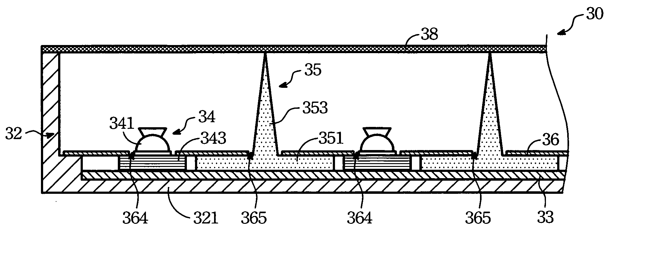
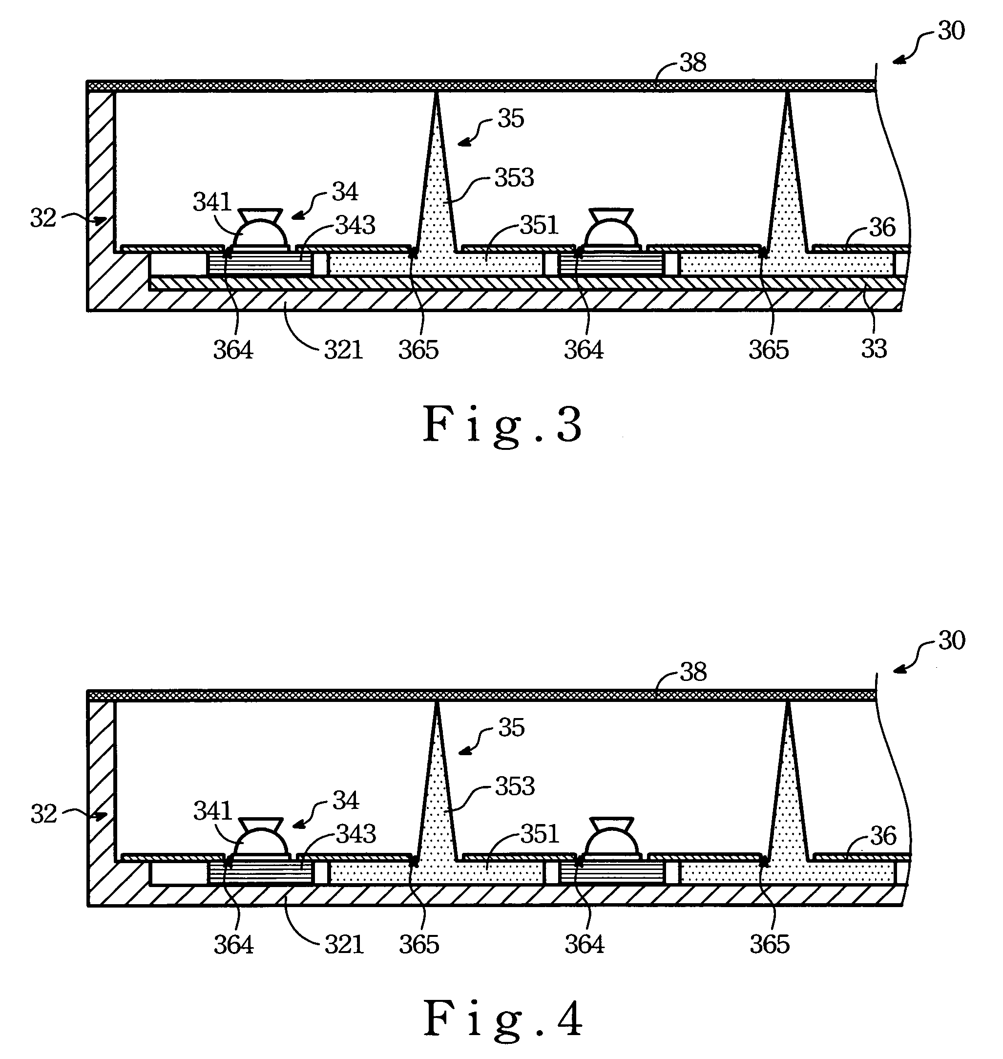
[0026]Referring to FIG. 3, a fragmentary sectional view of the preferred embodiment of an LED module 30 according to the present invention is shown to include a housing 32, a circuit board 33, at least one LED 34 (two shown in the figure), at least one support member 35 (two shown in the figure), a light reflective plate 36, and a light diffusing plate 38. The LEDs 34 shown in FIG. 3 can be employed in the light emitting lamps or signal indicator. They can also be disposed behind the display of an LCD device, thereby serving as a backlight module for illuminating the display.

[0027]The housing 32 has a base plate 321. The circuit board 33 is disposed on the base plate 321, and is electrically connected to the LEDs 34 so as to control the activation of the LEDs 34. In some embodiments (not shown here), the circuit board 33 is used for controlling the display of an LCD device, in which the display is disposed above the LED module 30.

[0028]In FIG. 3, each of the LEDs 34 has a lower moun...


PUM


Abstract

An LED module includes a housing, a support member disposed in the housing and having a lower portion supporting a reflective plate thereabove, and a cone-shaped protrusive portion projecting upwardly from the lower portion to support a diffusing plate thereabove so as to prevent the occurrence of downward bending of the middle portions of the reflective and diffusing plates due to their weights.

Description

FIELD OF THE INVENTION[0001]The present invention relates to a light emitting diode (LED) module, more particularly to an LED module with a support member to prevent downward bending of light reflective and diffusing plates therein.BACKGROUND OF THE INVENTION[0002]Due to rapid advance in the electronic manufacture technology, a breakthrough in the light-production effect of the LED helps to improve the display ability of the LCD screens. Technically speaking, the LED has presently reached the extent of serving half the ability of cold cathode tube. It is hoped that by the year 2005, the light-production effect of the LED may exceed than that of the cold cathode tube. Due to swift response and since the LED can emit visible light, such as red, blue and green, the high cost color filters presently used in the LCD screen are likely replaced by the LEDs in the near future so as to provide wonderful images and sufficient brightness to the LCD screen. In view of lesser power consumption b...

Claims


Application Information

Patent Timeline
Patent Type & Authority Patents(United States)
IPC IPC(8): F21V7/04F21K99/00
CPCF21K9/00G02F1/133608G02F1/133603G02F1/133605F21Y2101/02G02F1/133611G02F2201/54F21Y2115/10
Inventor CHOU, SHEN-HONG
Owner AU OPTRONICS CORP
Why Eureka
Try Eureka