
A Thin Plate Heating Furnace Self-propelling Steel Rods

A technology for heating furnaces and steel rods, applied in heat treatment furnaces, furnaces, furnace types, etc., can solve problems such as harsh working environment, high working intensity, troublesome operation, etc., improve the on-site working environment, save manpower and material resources, and move quickly and accurately Effect

Active Publication Date: 2018-07-06
湖北楠田工模具科技有限公司
View PDF2 Cites 0 Cited by
  • Summary
  • Abstract
  • Description
  • Claims
  • Application Information

AI Technical Summary

Problems solved by technology

[0002] In the plate heat treatment workshop, the heating furnace is an indispensable equipment. In the traditional heating furnace, especially for the heat treatment of thinner plates, many steel bars are used to send the plate into the furnace body. The traditional The best way is to use the driving device to push the push steel rods carrying the plates into the furnace body together, so that many push steel rods will accumulate in the furnace body after a long time, and workers need to use tools to fish them out from the side door. Large, time-consuming and labor-intensive. At the same time, the heated high-temperature thin plates also need to be fished out one by one by on-site workers with tools. The operation is very troublesome, and the on-site working environment is harsh

Method used


Image

  • A Thin Plate Heating Furnace Self-propelling Steel Rods
  • A Thin Plate Heating Furnace Self-propelling Steel Rods
  • A Thin Plate Heating Furnace Self-propelling Steel Rods

Examples


Embodiment Construction

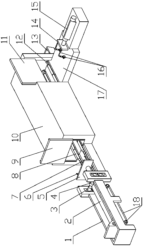
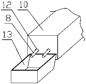
[0013] see Figure 1-Figure 3 , the present invention is a kind of thin-plate heating furnace that pushes steel bar automatically, has furnace body 10, and furnace body front part is provided with the furnace door 9 that slides up and down, is provided with two parallel furnace body length directions along the whole furnace body bottom. Arranged push steel bar groove 7, the front end of this push steel rod groove protrudes from the furnace door for a section, the front end of the push steel rod groove is provided with a push steel rod driving device, and the rear end wall of the body of furnace is provided with two push rods. Steel rod outlet hole 12, two push steel rod outlet holes are respectively docked with two push steel rod grooves, and the outside of the two push steel rod outlet holes is provided with a push steel rod collection box 13; There is a thin plate outlet, the thin plate outlet is provided with a discharge door 11 that slides up and down, the outside of the t...


PUM


Abstract

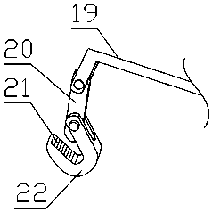
The invention relates to a sheet heating furnace capable of automatically discharging steel pushing rods. The sheet heating furnace has a furnace body, wherein a furnace door sliding up and down is arranged in a front part of the furnace body; two steel pushing rod grooves arranged in parallel are formed in the bottom of the furnace body; front ends of the steel pushing rod grooves extend out a section from the furnace door; steel pushing rod driving devices are arranged at the front ends of the steel pushing rod grooves; two steel pushing rod outlet holes are formed in a rear end wall of the furnace body; steel pushing rod collecting boxes are arranged outside the two steel pushing rod outlet holes; a sheet outlet is formed in a tail side wall of the furnace body; a discharge door sliding up and down is arranged on the sheet outlet; a material table is arranged at the outer part of the sheet outlet; a sheet pulling device is arranged on the outer side of the material table; the sheet pulling device is provided with a pulling cylinder; an output end of the pulling cylinder is connected with a mounting base plate; two hooks are arranged on the mounting base plate side by side; the two hooks are arranged toward the sheet outlet. The sheet heating furnace provided by the invention is novel and delicate in structural design and simple and convenient to operate, and can greatly reduce work environment and work intensity of field operators.

Description

technical field [0001] The invention relates to the technical field of metal heat treatment process equipment, in particular to a thin plate heating furnace for automatically pushing steel rods. Background technique [0002] In the plate heat treatment workshop, the heating furnace is an indispensable equipment. In the traditional heating furnace, especially for the heat treatment of thinner plates, many steel bars are used to send the plate into the furnace body. The traditional The best way is to use the driving device to push the push steel rods carrying the plates into the furnace body together, so that many push steel rods will accumulate in the furnace body after a long time, and workers need to use tools to fish them out from the side door. Large, time-consuming and laborious. At the same time, the heated high-temperature thin plates also need to be fished out one by one by on-site workers with tools. The operation is very troublesome, and the on-site working environm...

Claims


Application Information

Patent Timeline
Patent Type & Authority Patents(China)
IPC IPC(8): C21D9/46
CPCC21D9/46
Inventor 潘文福刘海松
Owner 湖北楠田工模具科技有限公司
Learn More