Anti-breaking chain joint structure

A joint structure and connection structure technology, applied in the direction of belts/chains/gears, chain elements, mechanical equipment, etc., can solve problems such as the failure of the connection between the chain and the target component, affecting the normal operation of the equipment, and the separation of the chain and the joint, so as to ensure the use , Protecting safety and avoiding safety accidents

Pending Publication Date: 2017-10-27
GUANGZHOU FUBEIZHI MACHINERY EQUIP CO LTD
View PDF5 Cites 0 Cited by
  • Summary
  • Abstract
  • Description
  • Claims
  • Application Information

AI Technical Summary

Problems solved by technology

Its disadvantages are: in the process of use, due to the influence of the partial load on the chain, the circlip may break away and fail, causing the pin to come out from the joint and the chain plate, causing the chain to separate from the joint, and making the gap between the chain and the target component connection failure, affecting the normal operation of the equipment and even causing safety accidents

Method used


Image

  • Anti-breaking chain joint structure
  • Anti-breaking chain joint structure
  • Anti-breaking chain joint structure

Examples


Embodiment 1

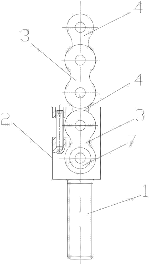
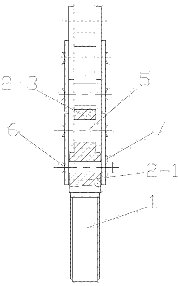
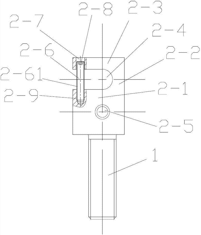
[0031] see Figure 1-Figure 3 The anti-break chain joint structure of this embodiment includes a joint 2, a pin shaft 6 and a snap spring 7, and the first connection end 2-1 of the joint 2 is connected to the two chain plates at the end of the chain through the pin shaft 7. The circlip 7 is arranged at the end of the pin shaft 6; the chain is formed by sequentially connecting the inner chain plate 4 and the outer chain plate 3 through the sleeve roller 5, wherein the first connecting end 2-1 of the joint 2 The two outer chain plates 3 at the end of the chain are connected by a pin 6; the first connecting end 2-1 of the joint 2 is provided with a pin hole 2-5 for passing the pin 6. The first connecting end 2-1 of the joint 2 is provided with a safety lock hole 2-4 above the pin shaft 6, and the sleeve roller 5 located above the pin shaft 6 in the chain passes through the safety lock hole 2 -4.

[0032] see Figure 1-Figure 3 , the outer side of the safety lock hole 2-4 has a...

Embodiment 2

[0039] The difference between this embodiment and embodiment 1 is that in this embodiment:

[0040] see Figure 4-Figure 8 , the second vertical connecting section is a connecting plate 2-10, and the detachable connecting structure includes an upper connecting screw 2-102 connecting the upper end of the connecting plate 2-10 to the transverse connecting section 2-3 and connecting The lower end of the connecting plate 2-10 is connected to the lower connecting screw 2-103 on the first connecting end 2-1 of the joint 2. By adopting the second vertical connecting section with the above-mentioned structure, the connection is more firm, which can effectively prevent the second vertical connecting section from falling off.

[0041] see Figure 4-Figure 8 , the connecting plate 2-10 includes a main body 2-101, the main body 2-101 is provided with a first semicircular groove 2-104 on the side facing the first vertical connecting section 2-2, the first vertical The connecting section...

Embodiment 3

[0044] The difference between this embodiment and embodiment 1 is that in this embodiment:

[0045] see Figure 9-Figure 11 , there are two safety lock holes, which extend along the length direction of the chain and are respectively the first safety lock hole 2-14 and the second safety lock hole 2-16, wherein the first safety lock hole 2-14 is located at Above the second safety lock hole 2-16; the first safety lock hole 2-14 is set outside the first sleeve roller 5-1, and the second safety lock hole 2-16 is set on the second Outside the sleeve roller 5-2; there are also two transverse connecting sections, which are the first transverse connecting section 2-13 above the first safety lock hole 2-14 and the second safety lock hole 2-16. The upper second transverse connecting segment 2-15. With such a design, when the pin shaft 6 is disengaged, more sleeve rollers can cooperate with the safety keyhole to share the load, and the safety protection effect is better.

[0046] see ...


PUM


Abstract

The invention discloses an anti-breaking chain joint structure which comprises a joint, a hinge pin and a clamp spring. A first connecting end of the joint is connected onto two chain plates at the ends of a chain by the hinge pin, and the clamp spring is arranged at an end of the hinge pin. The anti-breaking chain joint structure is characterized in that a safety lock hole is formed in the first connecting end of the joint and is particularly formed in a position above the hinge pin, and a sleeve roller, which is positioned above the hinge pin, in the chain penetrates the safety lock hole. The anti-breaking chain joint structure has the advantages that the safety lock hole and the sleeve roller can be matched with each other to carry out bearing when the hinge pin is separated from the anti-breaking chain joint structure, accordingly, reliable connection between the joint and the chain still can be guaranteed, the safety of target components can be effectively protected, and safety accidents can be prevented.

Description

technical field [0001] The invention relates to a chain joint structure, in particular to an anti-break chain joint structure. Background technique [0002] In the field of mechanical applications, it is often necessary to use the chain as a power transmission component to suspend or pull the target component, such as the lifting drive mechanism of the vehicle loading plate in the three-dimensional parking device, the lifting mechanism of the fork in the forklift, etc., in these In the application, the end of the chain needs to be connected with the target component through the chain joint structure. [0003] The existing chain joint structure usually consists of a joint, a pin shaft and a jumper, wherein one end of the joint is connected to the two chain plates at the end of the chain through a pin, and the jumper is arranged on the end of the pin to Prevent the pin shaft from breaking away from the structure and chain plate in the axial direction. Its disadvantages are: ...

Claims


Application Information

Patent Timeline
Patent Type & Authority Applications(China)
IPC IPC(8): F16G13/20F16G15/10
CPCF16G13/20F16G15/10
Inventor 陈江桦贾锦程
Owner GUANGZHOU FUBEIZHI MACHINERY EQUIP CO LTD
Why Eureka
Try Eureka