Low Noise Lensless Imaging Method

An imaging method and lensless technology, applied in logic circuits using specific components, logic circuits using optoelectronic devices, instruments, etc., can solve problems affecting image signal-to-noise ratio and high sensitivity, so as to improve signal-to-noise ratio and solve The effect of the noise sensitivity problem

Active Publication Date: 2020-05-05
ACAD OF OPTO ELECTRONICS CHINESE ACAD OF SCI
View PDF3 Cites 0 Cited by
  • Summary
  • Abstract
  • Description
  • Claims
  • Application Information

AI Technical Summary

Problems solved by technology

Half of its area is light-transmitting and has a high luminous flux. However, the URA-based lensless camera is more sensitive to noise, which will affect the signal-to-noise ratio of the final reconstructed image.

Method used


Image

  • Low Noise Lensless Imaging Method
  • Low Noise Lensless Imaging Method

Examples


Embodiment Construction

[0017] The technical solutions in the embodiments of the present invention will be clearly and completely described below in conjunction with the accompanying drawings in the embodiments of the present invention. Obviously, the described embodiments are only some of the embodiments of the present invention, not all of them. Based on the embodiments of the present invention, all other embodiments obtained by persons of ordinary skill in the art without making creative efforts belong to the protection scope of the present invention.

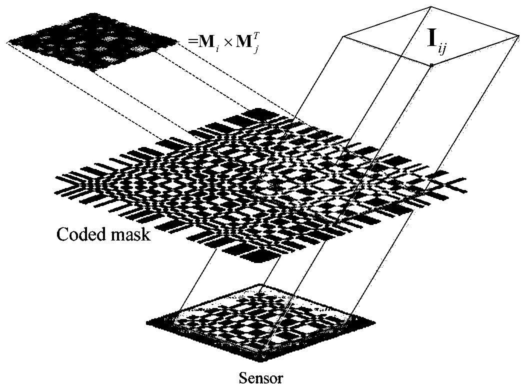
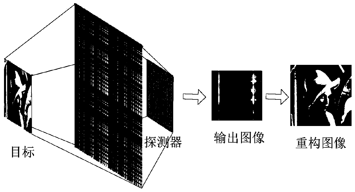
[0018] figure 2 It is a schematic diagram of a low-noise lensless imaging method provided by an embodiment of the present invention. Such as figure 2 As shown, after the detector is powered on, it records the light emitted by the target and passes through the coded template, and the output pattern is processed to reconstruct the image of the target after being correlated with the coded pattern.

[0019] The key part of the embodiment of the pre...


PUM


Abstract

The invention discloses a low-noise lens-free imaging method, comprising: after the detector is powered on, recording the light emitted by the target and passing through the coding template, and reconstructing the image of the target after the output pattern is correlated with the coding pattern; The effective array size of the detector is larger than half of the pattern size of the coding template; The distribution of the square unit is represented by a matrix generated by the outer product of two pseudo-random vectors composed of 0 and 1. The 0 and 1 in the matrix represent that the encoding pattern cannot Light-transmitting and light-transmitting, the number of block units that cannot pass through light is greater than the number of block units that can pass through light. This scheme is based on a specific encoding template, which can solve the problem of sensitivity to noise of lensless cameras based on URA templates, thereby improving the signal-to-noise ratio of reconstructed images.

Description

technical field [0001] The invention relates to the technical field of lensless imaging, in particular to a low-noise lensless imaging method. Background technique [0002] Lensless imaging is a technology that uses a special template instead of a traditional lens to achieve indirect imaging. The principle is that after the light emitted by the luminous point passes through the template, a corresponding shadow pattern is projected on the detector. The shadow pattern records the position and luminous intensity information of the luminous point, and the position is different, and the pattern is also different. There is no correlation between the different patterns. The detector records the superimposed pattern, and the intensity of the light-emitting points at different positions can be calculated through correlation calculation, so as to obtain the corresponding image. [0003] There are many forms of templates, including Fresnel zone plate, URA, random binary coding templa...

Claims


Application Information

Patent Timeline
Patent Type & Authority Patents(China)
IPC IPC(8): G03B41/00G02F3/00
CPCG02F3/00G03B41/00
Inventor 王建威吕群波李伟艳张丹丹裴琳林刘扬阳赵娜
Owner ACAD OF OPTO ELECTRONICS CHINESE ACAD OF SCI
Why Eureka
Try Eureka