

Current overload protector structure
Patent Information
- Authority / Receiving Office
- CN · China
- Current Assignee / Owner
- GUANGZHOU SENBAO ELECTRICAL APPLIANCES
- Publication Date
- 2017-10-27
- Estimated Expiration
- Not applicable · inactive patent
Smart Images
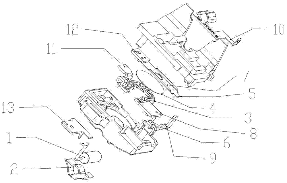
Figure 1 
Figure 2
Abstract
Description
technical field
[0001] The invention relates to a protection device for electrical equipment, in particular to a structure of a current overload protector. Background technique
[0002] During the use of many electrical equipment, there will be excessive line current caused by excessive load, short circuit of the line, and aging of equipment insulation; if the equipment continues to be used when the line current is too large, it will cause it to heat up or even burn out. Long-term exposure to strong electricity will also reduce the insulation performance of the line or burn the line.
[0003] Therefore, electrical equipment is generally connected in series with an overload protector. When an abnormal situation occurs during the operation of the electrical equipment and the current is too large, the excessive current will increase the temperature of the line, and the bimetal in the overload protector will be heated. And deformation, the action of deformation makes the bimeta...