
Method for monitoring the operation of a gas turbine

a gas turbine and operation monitoring technology, applied in the direction of measuring devices, instruments, testing of jet-propulsion engines, etc., can solve the problems of structural mechanical damage, negative influence on stability and integrity, and brick cracks that may subsequently occur, so as to avoid unnecessary downtime of gas turbine for visual inspection

Inactive Publication Date: 2019-03-26
SIEMENS ENERGY GLOBAL GMBH & CO KG
View PDF17 Cites 2 Cited by
  • Summary
  • Abstract
  • Description
  • Claims
  • Application Information

AI Technical Summary

Benefits of technology

The invention provides a method for monitoring the operation of a gas turbine without the need for visual inspections during downtimes. The method uses an acceleration sensor on the component to detect vibrations and sophisticated processing techniques to establish an overall vibration period by counting the time intervals with the highest amplitudes. This approach helps to identify potential issues with the gas turbine and increase its availability for use.

Problems solved by technology

Such monitoring processes are often used in gas turbines since combustion vibrations may occur during the combustion of gaseous and liquid fuels, which combustion vibrations may put components surrounding the combustion space into motion.
Nevertheless, those accelerations of the combustor which do not trigger a “trip” may also lead to structure-mechanical damage.
In the case of annular combustors lined with ceramic thermal shielding bricks, cracks may subsequently occur in the bricks, having a negative influence on the stability and integrity thereof.
Moreover, consequential damages may occur, for example in the form of scaling on the support structure of the bricks as a result of hot-gas entry into the cracks.
If the defects are present, the damaged components or parts are subsequently replaced.
However, the visual inspection of the gas turbine requires downtimes, which reduce the availability of the gas turbine.
In this case, the visual inspection was performed unnecessarily.

Method used


Image

  • Method for monitoring the operation of a gas turbine
  • Method for monitoring the operation of a gas turbine

Examples


Embodiment Construction

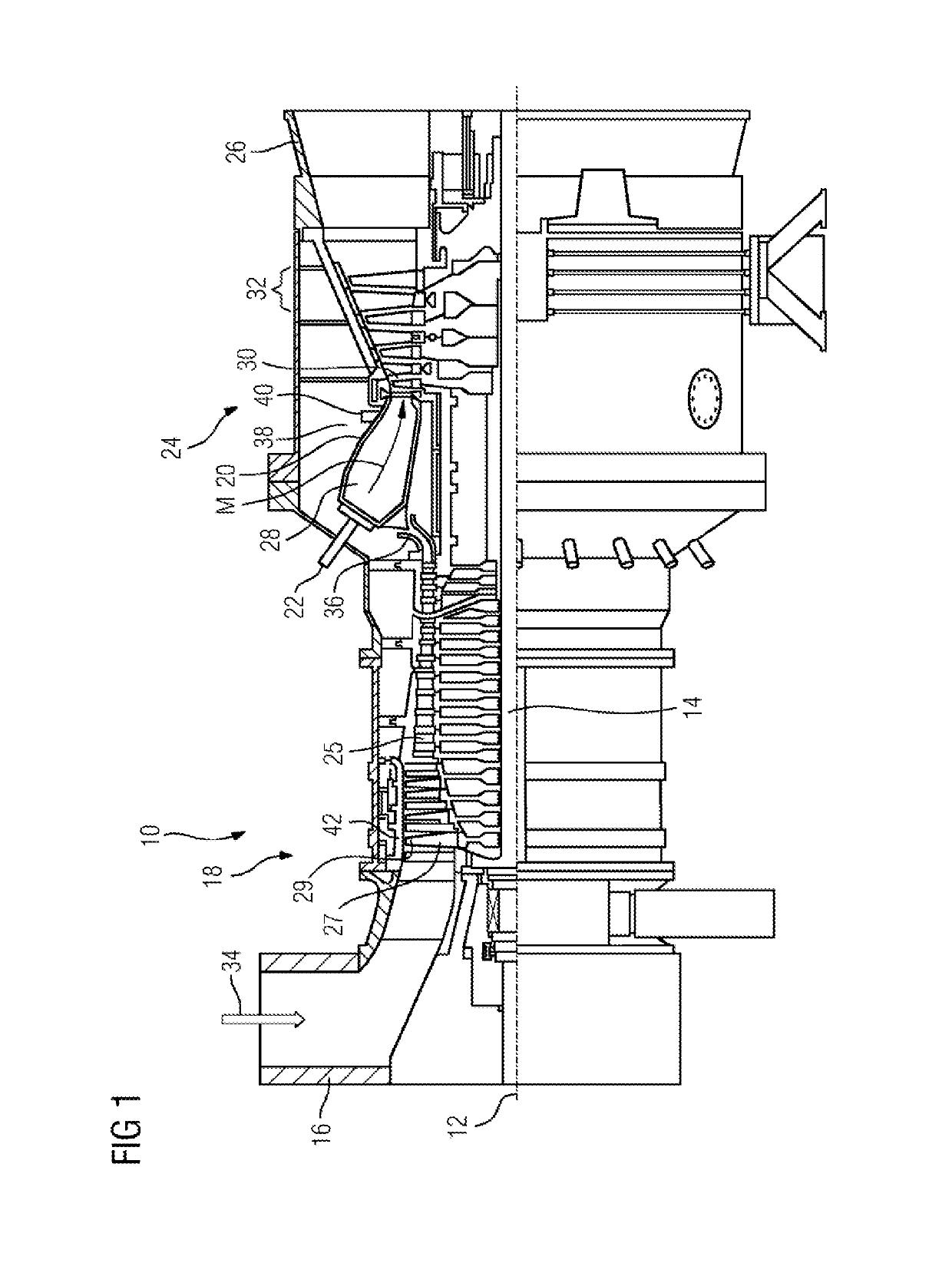
[0026]FIG. 1 shows a stationary gas turbine 10 in longitudinal partial section. The gas turbine 10 has, inside it, a rotor 14 which is mounted rotatably about an axis of rotation 12 and which is also referred to as a turbine rotor. Along the rotor 14 there are, in succession, an intake housing 16, an axial turbocompressor 18, a toroidal annular combustor 20 comprising a plurality of burners 22 arranged rotationally symmetrically with respect to one another, a turbine unit 24 and a turbine exhaust housing 26.

[0027]The axial turbocompressor 18 comprises a ring-shaped compressor duct 25 comprising successive compressor stages—in the manner of a cascade—including rotor blade rings and guide vane rings. The rotor blades 27 arranged on the rotor 14 lie with their free-ending blade airfoil tips 29 opposite an outer duct wall 42 of the compressor duct 25. The compressor duct 25 opens, via a compressor outlet diffuser 36, into a plenum 38. The annular combustor 20 with its combustion space 2...


PUM


Abstract

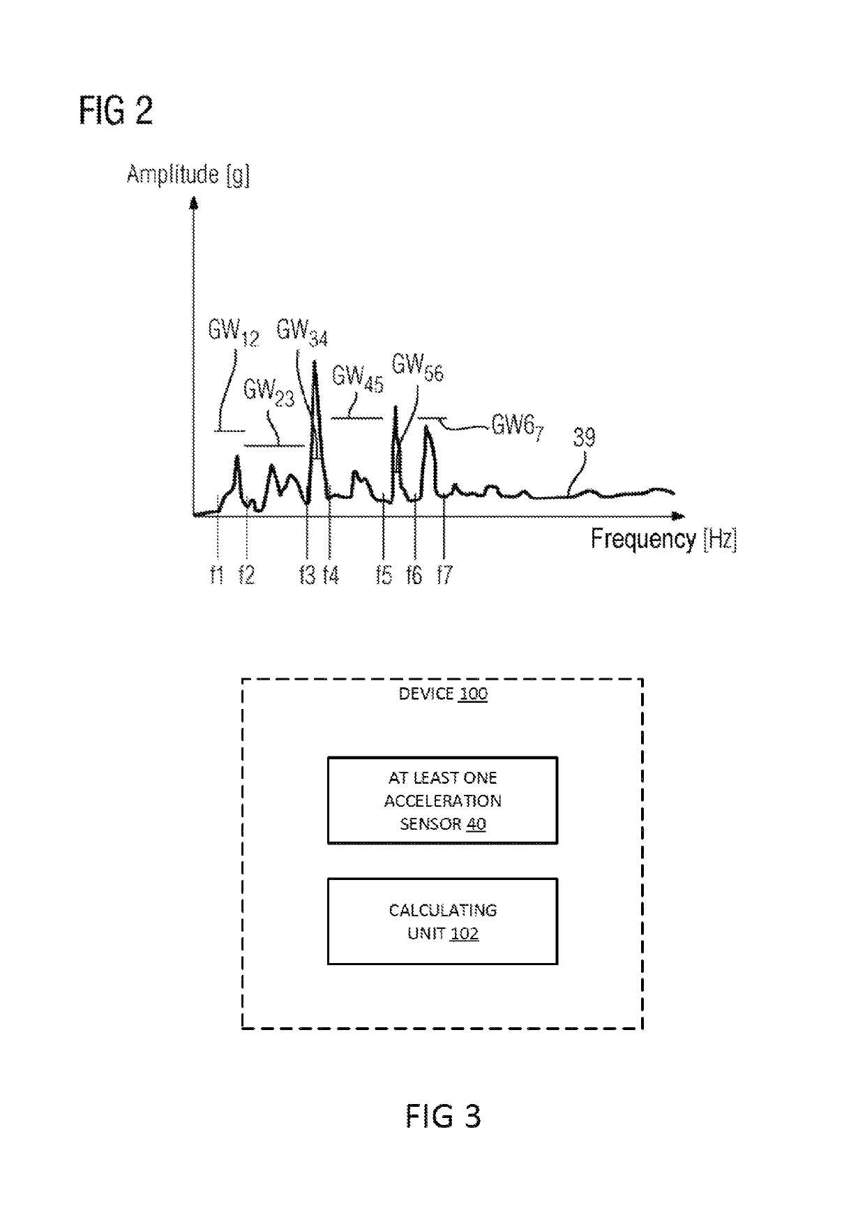
A method for monitoring the operation of a gas turbine is provided, in which component vibrations are detected during the operation of the gas turbine by an acceleration sensor arranged on the component, a plurality of signal sections being determined by a plurality of frequency bands fb from the signal forwarded and processed by the acceleration sensor. To avoid an unnecessary shutdown of the gas turbine to perform an inspection which subsequently proves unnecessary, thereby increasing the availability of the gas turbine, a total vibration period is determined by adding together the vibration periods of signal sections during which the amplitudes of the signal sections concerned are greater than a frequency band-specific threshold.

Description

CROSS REFERENCE TO RELATED APPLICATIONS[0001]This application is the US National Stage of International Application No. PCT / EP2013 / 065732 filed Jul. 25, 2013, and claims the benefit thereof. The International Application claims the benefit of German Application No. DE 102012215410.8 filed Aug. 30, 2012. All of the applications are incorporated by reference herein in their entirety.FIELD OF INVENTION[0002]The invention relates to a method for monitoring the operation of a gas turbine, in which component vibrations are detected during the operation of the gas turbine by an acceleration sensor arranged on the component and the signal forwarded from the acceleration sensor establishes a plurality of signal sections by means of a plurality of frequency bands.BACKGROUND OF INVENTION[0003]Such monitoring processes are often used in gas turbines since combustion vibrations may occur during the combustion of gaseous and liquid fuels, which combustion vibrations may put components surrounding...

Claims


Application Information

Patent Timeline
Patent Type & Authority Patents(United States)
IPC IPC(8): G01H1/16G01M15/14G01H1/00G01H17/00
CPCG01M15/14G01H17/00G01H1/003
Inventor BOTTCHER, ANDREASKAUFMANN, PETERKRIEGER, TOBIASVAN KAMPEN, JAAP
Owner SIEMENS ENERGY GLOBAL GMBH & CO KG
Learn More