Shock Absorbing Structures for Ceiling Systems

A technology of suspended ceiling and connecting rod, which is applied in the field of building keel and light steel suspended ceiling system to achieve the effect of enhancing seismic performance, ensuring smooth progress, and offsetting adverse effects

Active Publication Date: 2019-03-12
BEIJING NEW BUILDING MATERIALS PLC
View PDF6 Cites 1 Cited by
  • Summary
  • Abstract
  • Description
  • Claims
  • Application Information

AI Technical Summary

Problems solved by technology

[0003] The present invention aims to solve the problems described above

Method used


Image

  • Shock Absorbing Structures for Ceiling Systems
  • Shock Absorbing Structures for Ceiling Systems

Examples


Embodiment Construction

[0019] In order to make the purpose, technical solutions and advantages of the embodiments of the present invention clearer, the technical solutions in the embodiments of the present invention will be clearly and completely described below in conjunction with the drawings in the embodiments of the present invention. Obviously, the described embodiments It is a part of embodiments of the present invention, but not all embodiments. Based on the embodiments of the present invention, all other embodiments obtained by persons of ordinary skill in the art without making creative efforts belong to the protection scope of the present invention. It should be noted that, in the case of no conflict, the embodiments in the present application and the features in the embodiments can be combined arbitrarily with each other.

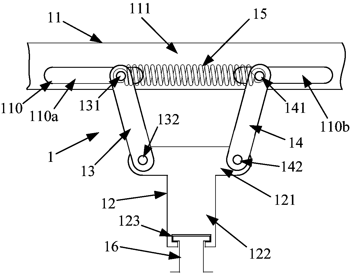
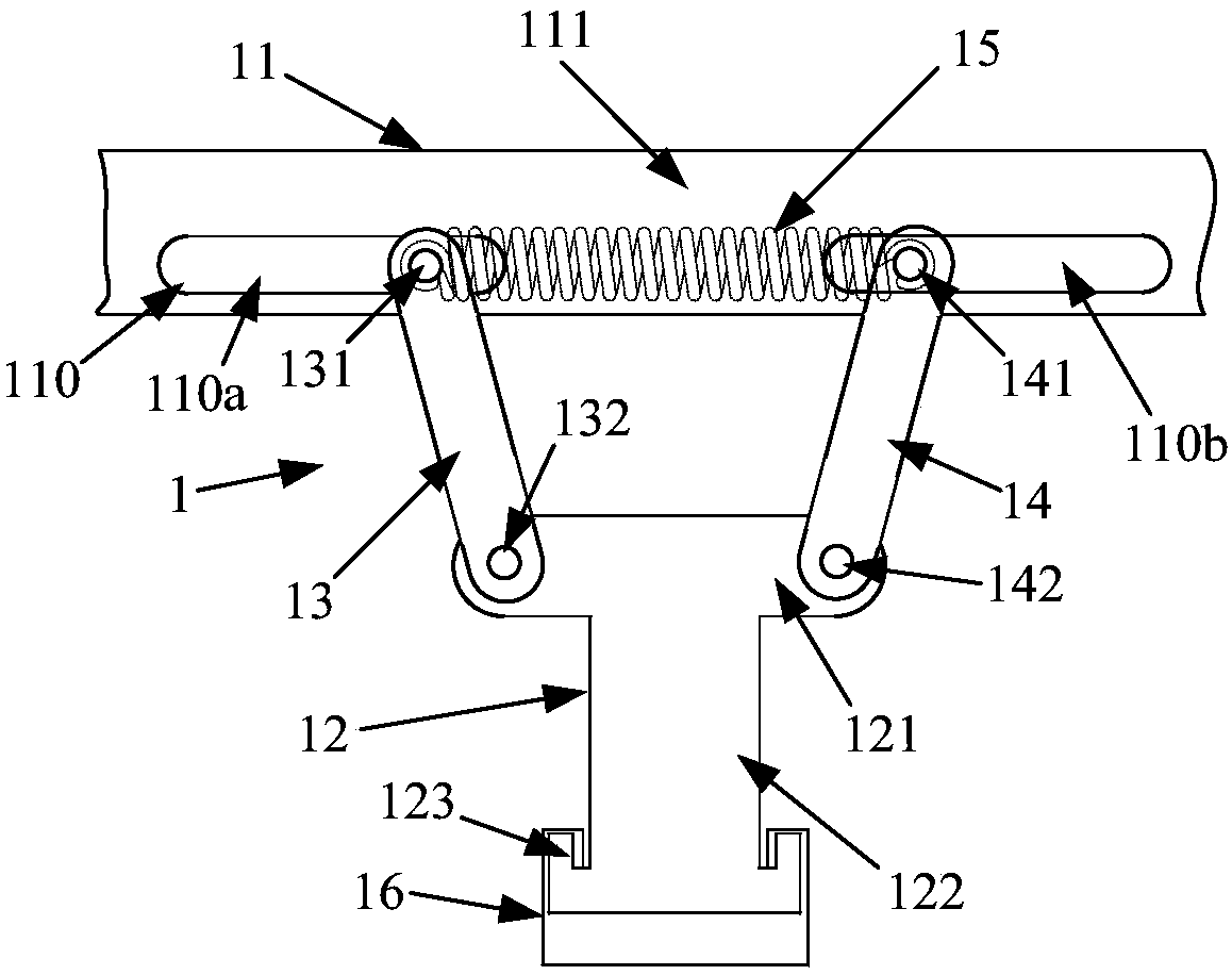
[0020] In order to improve the anti-seismic performance of the ceiling system, the invention provides a shock absorbing structure for the ceiling system, by setting a ...


PUM


Abstract

Provided is a vibration-damping structure (1) for a dropped ceiling system, comprising: a first frame member (11); at least one T-shaped connector (12); at least one first link rod (13); at least one second link rod (14); at least one spring (15); and at least one second frame member (16). The vibration-damping structure (1) for a dropped ceiling system can reduce negative influence of vibration on a dropped ceiling system, and enhance vibration resistance of the dropped ceiling system.

Description

technical field [0001] The invention relates to the technical field of building keels, in particular to the technical field of light steel ceiling systems. Background technique [0002] The current light steel keel ceiling is made by connecting the bearing keel and the covering keel with connectors to form a frame, and then covering it with plasterboard. However, in earthquake-prone areas, the impact resistance and deformation resistance of traditional ceiling keels are average. When an earthquake occurs, it is not enough to support the ceiling frame, and the ceiling is prone to deformation or even collapse, which poses a major safety hazard. On the other hand, in the process of setting up and installing the ceiling system, no matter how careful you are, there will often be vibrations between the keels or between the keel and the connecting parts, causing deformation or even scrapping of the keels or connecting parts; The assembled parts need to be dismantled and reworked, ...

Claims


Application Information

Patent Timeline
Patent Type & Authority Patents(China)
IPC IPC(8): E04B9/06E04B1/98E04H9/02
CPCE04B9/16
Inventor 武发德许刚孙佳莫芝赵红玲
Owner BEIJING NEW BUILDING MATERIALS PLC
Why Eureka
Try Eureka