Device for detecting detected object

A detection body and equipment technology, which is applied in the direction of measuring devices, instruments, and material analysis through electromagnetic means, can solve the problem that the conveyor belt is not suitable for cylindrical detection bodies, and achieve simple and reliable placement and removal, and simple maintenance Effect

Inactive Publication Date: 2017-10-31
H & T MARSBERG
View PDF1 Cites 0 Cited by
  • Summary
  • Abstract
  • Description
  • Claims
  • Application Information

AI Technical Summary

Problems solved by technology

[0003] Although it is known to supply test bodies to radiation sources by conveyor belts, as shown in EP0311177B1 especiall

Method used


Image

  • Device for detecting detected object

Examples


Embodiment Construction

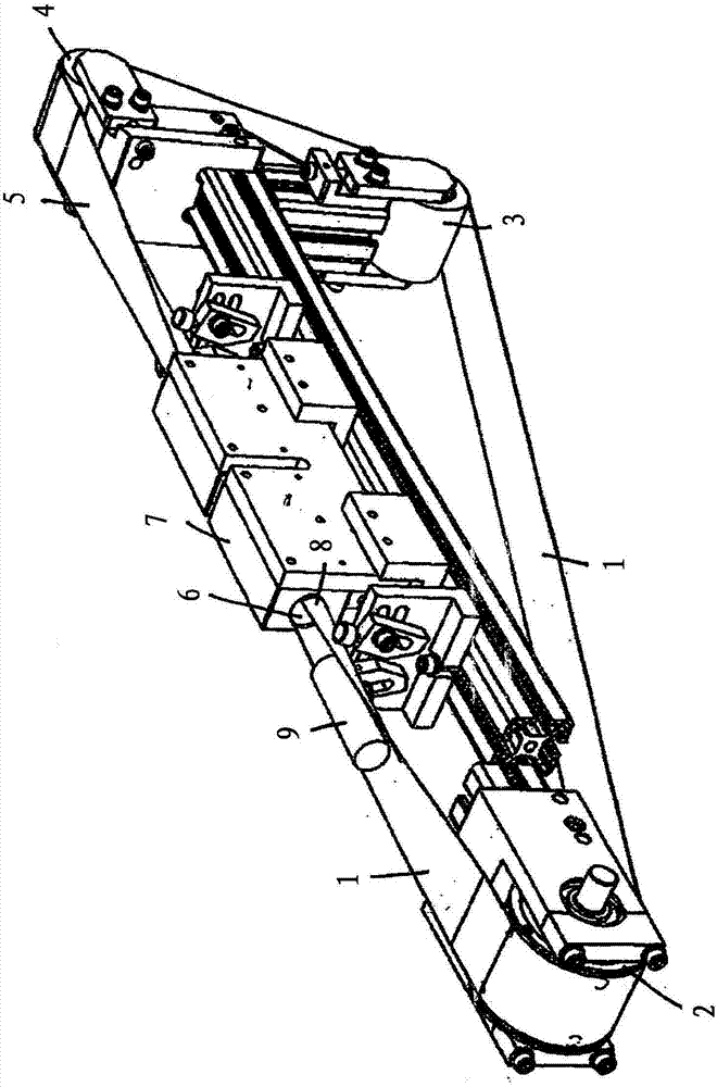
[0010] The flat conveyor belt 1 is guided as an endless endless belt via two, three or more deflection rollers 2 , 3 , 4 . The electrically driven conveyor belt 1 forms an upper horizontal region 5 which extends through the test channel 6 of the eddy current test device 7 .

[0011] The detection channel 6 has a cylindrical shape, the horizontal axis of which is parallel to the longitudinal direction of the horizontal strip region 5 . The conveyor belt 1 is deformed into a groove 8 through the detection channel 6, and the groove is a partial circle at an angle of 180-300 degrees in its cross section, so the groove 8 of the conveyor belt surrounds a cylindrical detection body 9, and the detection The bodies are placed on the conveyor belt 1 in such a way that the longitudinal direction of the test bodies, in particular their longitudinal axes, is parallel to the longitudinal direction of the conveyor belt 1 and preferably coaxial to the axis of the test channel 6 .

[0012] Th...


PUM


Abstract

The invention relates to a device for detecting a detected object through a detection device, particularly an eddy current detection device. The detected object moves to pass through a detection channel of the detection device, a conveyer belt runs to pass through the detection channel, the conveyer belt passes through the detection channel and/or a guiding element arranged in the front of and/or in the detection channel and deforms into a trench, and the trench encloses the detected object at least in a detection road segment area.

Description

technical field [0001] The invention relates to a device for testing a test body by means of a test device, in particular an eddy current test device, the test body being moved through a test channel of the test device. Background technique [0002] It is known to identify material defects of metal parts by eddy current testing. In this case, eddy currents are induced in the material to be tested and the change in electrical conductivity is measured. For discontinuously cylindrical test bodies having, for example, widenings or dips, it has been shown that the test bodies cannot be guided precisely through the test channel because the test bodies change their position, in particular their inclination. [0003] Although it is known to supply test bodies to radiation sources via conveyor belts, as shown in EP0311177B1 in particular for luggage, such conveyor belts are not suitable for precise guidance of cylindrical test bodies with external deviations. Contents of the inven...

Claims


Application Information

Patent Timeline
IPC IPC(8): G01N27/90
CPCG01N27/9026G01N27/9093G01N27/90
Inventor T·格特
Owner H & T MARSBERG
Why Eureka
Try Eureka