Developing box

A developing cartridge and developer technology, which is applied in the field of developing cartridges, can solve the problems such as high requirements on the assembly progress of the rotating shaft and increased cost.

Pending Publication Date: 2017-10-31
NINESTAR CORP
View PDF5 Cites 2 Cited by
  • Summary
  • Abstract
  • Description
  • Claims
  • Application Information

AI Technical Summary

Problems solved by technology

[0009] However, in the prior art, the contact state between the moving part and the touch part is controlled by setting an additional rotating shaft and rotating the moving part around the rotating shaft, which requires high assembly progress of the rotating shaft;

Method used


Image

  • Developing box
  • Developing box
  • Developing box

Examples


Embodiment 1

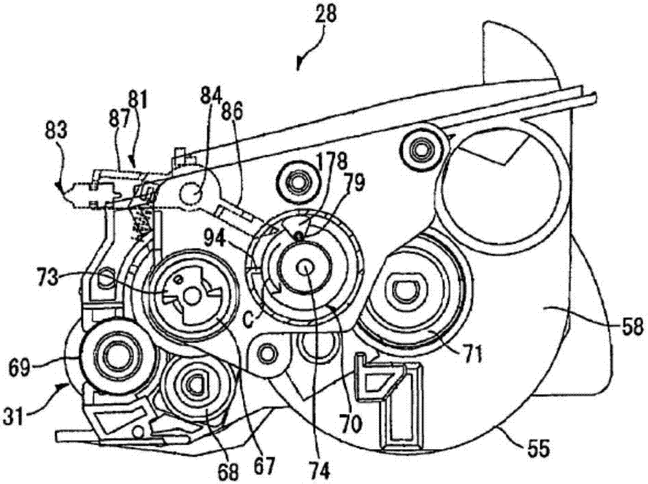
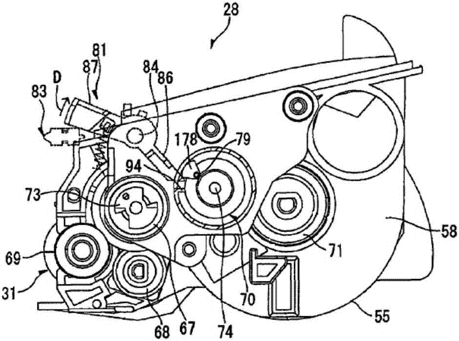
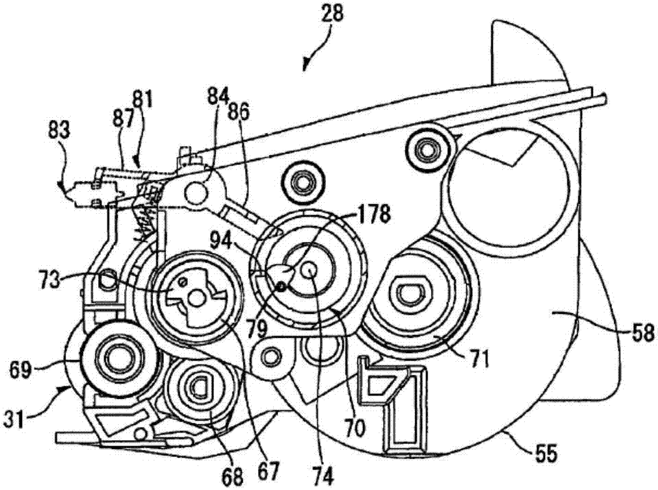
[0035] In this embodiment, a developing cartridge is provided. The developing cartridge can be applied to commonly used electrophotographic imaging devices such as printers, copiers and facsimile machines, and the overall structure of the developing cartridge is consistent with Figure 1 to Figure 3 The overall structure of the developing cartridge in is similar, so if there is no special instruction, the overall structure of the developing cartridge in this embodiment is the same as figure 1 the same or similar in . The developing cartridge of this embodiment specifically includes a powder bin for accommodating the developer, and also includes a counting mechanism and a transmission gear for transmitting power to the counting mechanism. The counting mechanism includes a first rotating member and a second rotating member.

[0036] Wherein, the transmission gear can at least mesh with one of the first rotating member and the second rotating member to transmit power to the count...

Embodiment 2

[0061] On the basis of the first embodiment above, the first rotating member can also be configured as a full-toothed gear structure, and the first rotating member and the second rotating member are not coaxially connected, but meshed with each other. Figure 7a It is a schematic diagram of the structure of the counting mechanism in the developing cartridge in the initial position provided by the second embodiment of the present invention. Figure 7b It is a schematic diagram of the structure of the counting mechanism in the developing cartridge in the final position provided by the second embodiment of the present invention. Such as Figure 7a and Figure 7b As shown, in this embodiment, the first rotating member 111 can be set as a full-toothed gear, and the second rotating member 112 can be a tooth-less gear, and the first rotating member 111 and the second rotating member 112 mesh, and the second rotating member 112 and The transmission gear 25 is engaged.

[0062] Spec...

Embodiment 3

[0072] In addition, an additional rotating member may also be provided to play a role of connection and transmission between the first rotating member and the second rotating member. Figure 8a It is a structural schematic diagram of the counting mechanism in the initial position of the developing cartridge provided by Embodiment 3 of the present invention. Figure 8b It is a structural schematic diagram of the counting mechanism in the developing cartridge provided by Embodiment 3 of the present invention at the final position. Such as Figure 8a and Figure 8b As shown, in this embodiment, in addition to the first rotating member 134 and the third rotating member 131, the counting mechanism also includes a second rotating member 132, the first rotating member 134 is a full tooth gear, the third rotating member 131 and the second rotating member Parts 132 are toothless gears, and the third rotating part 131 and the second rotating part 132 rotate coaxially, and can form a f...


PUM


Abstract

The invention provides a developing box. The developing box comprises a powder bin, a transfer gear and a counting mechanism, wherein the powder bin is used for accommodating a developing agent, the counting mechanism comprises a first rotation piece and a second rotation piece, a bulge is arranged on the first rotation piece and touches or does not touch a contact rod of an electronic imaging device for conversion under power of the transfer gear so as to achieve counting, the transfer gear at least can be engaged with one of the first rotation piece and the second rotation piece, the first rotation piece and the second rotation piece coaxially rotate or rotate in an engagement way, and the transfer gear is used for transferring power to the first rotation piece or the second rotation piece so that the second rotation piece rotates to a first position where the power is not prevented from being transferred to the first rotation piece to a second position where the power is prevented from being transferred to the first rotation piece. By the developing box, touch to the contact rod for many times can be achieved so as to transfer different information of the developing box; and meanwhile, the developing box is simple in structure and is relatively low in cost.

Description

technical field [0001] The invention relates to the technical field of printing, in particular to a developing box. Background technique [0002] At present, when laser printers, copiers, facsimile machines, and other electrophotographic imaging devices or printing equipment are developed and imaged, a detachable developing cartridge is usually used, and when the developing cartridge life expires, etc., by replacing the developing cartridge, Ensure the normal operation of printing and imaging equipment. [0003] At present, in order to realize the replacement of the developing cartridge, a counting mechanism is provided on the developing cartridge. The counting mechanism can be used in conjunction with the detection device in the electrophotographic imaging device, and indicates whether the developing cartridge loaded into the electrophotographic imaging device is a new developing cartridge. cartridge, allowing the print imaging device to calculate the life of a new develop...

Claims


Application Information

Patent Timeline
IPC IPC(8): G03G15/08
CPCG03G15/0896G03G21/1857
Inventor 杨浩曹建新
Owner NINESTAR CORP
Why Eureka
Try Eureka