Automatic counting and feeding mechanism for boxing drill bits

An automatic counting and drilling technology, applied in the direction of packaging automatic control, packaging, packaging protection, etc., can solve the problems of reducing product consistency, low degree of automation, and damage to staff.

Pending Publication Date: 2020-10-23
江苏爵克数控刀具有限公司
View PDF0 Cites 0 Cited by
  • Summary
  • Abstract
  • Description
  • Claims
  • Application Information

AI Technical Summary

Problems solved by technology

[0002] The traditional packaging of drill bits is usually done by manpower. Although some semi-automatic equipment has been added to improve the packaging efficiency to a certain extent, compared with completely unmanned automatic packaging, there are still defects: putting the drill bits into The process automation in the inner box is low, mainly manual counting and loading. Since the blade of the drill bit is relatively sharp, there is still a risk of injury to the staff when packing the box, and the number of drill bits loaded in each box depends on manual counting. There is a certain error rate, which reduces the consistency of the product;

Method used


Image

  • Automatic counting and feeding mechanism for boxing drill bits
  • Automatic counting and feeding mechanism for boxing drill bits
  • Automatic counting and feeding mechanism for boxing drill bits

Examples


Embodiment Construction

[0029] In order to deepen the understanding of the present invention, the present invention will be further described below in conjunction with the embodiments and accompanying drawings. The embodiments are only used to explain the present invention and do not constitute a limitation to the protection scope of the present invention.

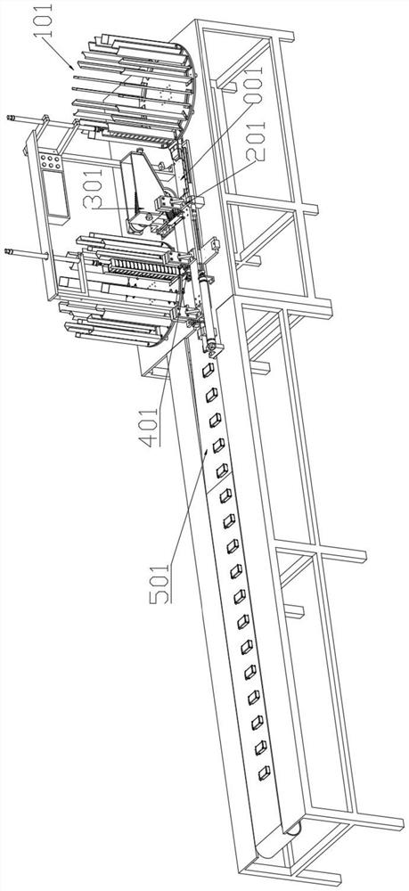
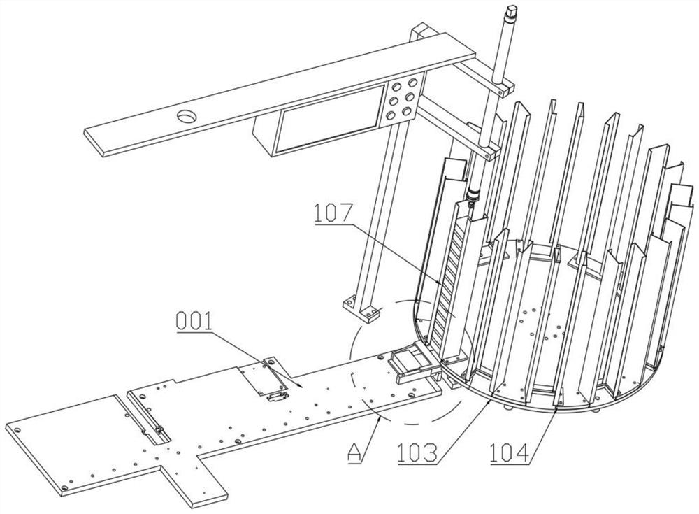
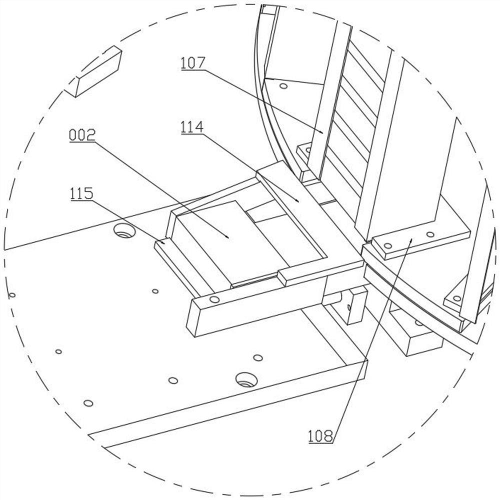
[0030] like Figure 1-13 As shown, an automatic counting and feeding mechanism for drill bit boxing includes a packaging machine working panel 001, two sets of turntable storage modules 101, linkage jaw modules 201, an automatic counting and feeding mechanism 301 and a floating upper The cover module 401 ; the end of the working panel 001 of the packaging machine is provided with a finished product conveyor belt 501 .

[0031] The turntable storage module The turntable storage module 101 includes a pneumatic indexing plate 102, the pneumatic indexing plate 102 is equipped with a lower fixed disc 103 and an upper rotating disc 104, the lower fixed...


PUM


Abstract

The invention discloses an automatic counting and feeding mechanism for boxing drill bits. The automatic counting and feeding mechanism comprises a drill bit storage box, a feeding rotating wheel, a temporary storage groove and a feeding air cylinder, drill bit grooves are evenly formed in the side face of the feeding rotating wheel in the circumferential direction, the drill bit grooves are semicircular grooves capable of containing only one drill bit, the feeding rotating wheel is installed on the lower wall of the drill bit storage box, the lower wall of the drill bit storage box is inclined downwards and extends clockwise to form a coating wall, the tail end of the coating wall is guided to the temporary storage groove through a material falling inclined plate, an inner box is placed on one side of the temporary storage groove, and a feeding push block is arranged on the other side of the temporary storage groove; the feeding air cylinder is arranged below the temporary storage groove, and a guide rod of the feeding air cylinder is horizontally and synchronously connected with the feeding push block. According to the automatic counting and feeding mechanism, the effect that thesingle drill bits fall down according to the queue is automatically achieved through rotation of the feeding rotating wheel, the drill bits can be effectively counted and enter the temporary storagegroove, the drill bits with the fixed number are pushed into the inner box through pushing of the feeding push block, and the problem that mistakes and omissions are generated during manual boxing isavoided.

Description

technical field [0001] The invention relates to the field of automatic packaging, and in particular relates to an automatic counting and feeding mechanism for drilling boxes. Background technique [0002] The traditional packaging of drill bits is usually done by manpower. Although some semi-automatic equipment has been added to improve the packaging efficiency to a certain extent, compared with completely unmanned automatic packaging, there are still defects: putting the drill bits into The process automation in the inner box is low, mainly manual counting and loading. Since the blade of the drill bit is relatively sharp, there is still a risk of injury to the staff when packing the box, and the number of drill bits loaded in each box depends on manual counting. There is a certain error rate, which reduces the consistency of the product; Contents of the invention [0003] The purpose of the present invention is to solve the above deficiencies in the prior art, and propos...

Claims


Application Information

Patent Timeline
IPC IPC(8): B65B35/30B65B35/36B65B35/40B65B57/20B65B7/28
CPCB65B7/28B65B35/30B65B35/36B65B35/40B65B57/20
Inventor 包顺华薛国新
Owner 江苏爵克数控刀具有限公司
Why Eureka
Try Eureka