Charging area display method, and wireless charger

A technology of wireless charger and charging area, applied in the direction of current collector, wireless communication, wireless communication service, etc., can solve the problem of difficulty in grasping the placement of mobile terminals

Active Publication Date: 2017-11-03
VIVO MOBILE COMM CO LTD
View PDF7 Cites 4 Cited by
  • Summary
  • Abstract
  • Description
  • Claims
  • Application Information

AI Technical Summary

Problems solved by technology

During use, it is often necessary for the user to adjust the position of the mobile terminal multiple times before charging can be performed, especially when mobile termi

Method used


Image

  • Charging area display method, and wireless charger
  • Charging area display method, and wireless charger
  • Charging area display method, and wireless charger

Examples


no. 1 example

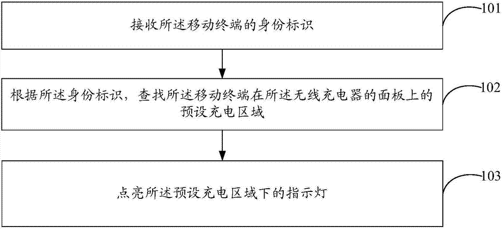
[0020] refer to figure 1 , which shows a flow chart of a method for displaying a charging area according to Embodiment 1 of the present invention, which may specifically include the following steps:

[0021] Step 101, receiving the identity of the mobile terminal.

[0022] In the embodiment of the present invention, the wireless charger can charge the mobile terminal placed on the panel. In order to realize the display method of the charging area in the embodiment of the present invention, there must be multiple indicator lights on the wireless charger. Specifically, the indicator lights can be The array arrangement is embedded under the panel of the wireless charger. For example, N times N (N is greater than or equal to 2) LED (Light Emitting Diode, light emitting diode) lights are embedded under the panel of the wireless charger as indicator lights.

[0023] In the embodiment of the present invention, the identity of the mobile terminal is identification information that u...

no. 2 example

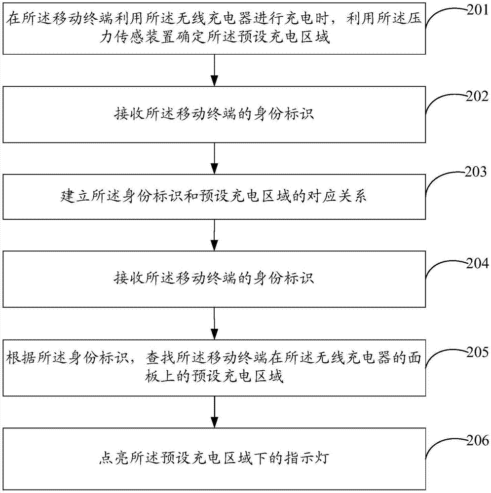
[0038] refer to figure 2 , which shows a flow chart of a method for displaying a charging area according to Embodiment 2 of the present invention, which may specifically include the following steps:

[0039]Step 201, when the mobile terminal is charged by the wireless charger, use the pressure sensing device to determine the preset charging area.

[0040] In the embodiment of the present invention, the panel of the wireless charger includes a pressure sensing device for predetermining the preset charging area of ​​the mobile terminal. The pressure sensing device can sense the pressing force. For example, the pressure sensing device can be attached to the bottom of the panel of the wireless charger, and a certain gap, at least 0.1 mm, should be kept between the panel of the wireless charger.

[0041] When the mobile terminal is charged by the wireless charger, the position of the receiving coil and the transmitting coil is realized by continuously adjusting the position of t...

no. 3 example

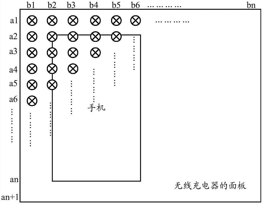
[0061] refer to image 3 , shows a schematic diagram of a wireless charger according to Embodiment 3 of the present invention.

[0062] In the embodiment of the present invention, the wireless charger includes a plurality of indicator lights for indicating the charging area. Specifically, the indicator lights can be embedded under the panel of the wireless charger in the form of an array, and are used to display that the mobile terminal is wirelessly charged. A preset charging area on the panel of the charger; wherein, the preset charging area is obtained by receiving the identification of the mobile terminal and finding it according to the identification.

[0063] For example, N times N (N is greater than or equal to 2) LED (Light Emitting Diode, light emitting diode) lights are embedded under the panel of the wireless charger as indicator lights.

[0064] In the embodiment of the present invention, preferably, the wireless charger further includes a pressure sensing device;...


PUM


Abstract

The embodiment of the invention provides a charging area display method, and a charger. The method is applied to the wireless charger. A plurality of indication lamps used for indicating charging areas are arranged below a panel of the wireless charger. The method comprises the following steps: receiving an identifier of a mobile terminal; according to the identifier, searching for a preset charging area for the mobile terminal on the panel of the wireless charger; and lightening the indication lamp below the preset charging area. The preset charging area is pre-determined for the mobile terminal placed on the panel of the wireless charger, so that when the mobile terminal needs to be charged in a wireless manner, a placement location of the mobile terminal needs not be adjusted every time to search for the charging area; and the indication lamps are used to prompt the preset charging areas for different mobile terminals, so that the mobile terminals can be placed in positions where the charging efficiencies are higher than the charging efficiencies in random placement positions, and the problem that the placement positions of the mobile terminals need to be adjusted for multiple times every time before charging is avoided.

Description

technical field [0001] The embodiments of the present invention relate to the technical field of mobile terminals, in particular to a method for displaying a charging area and a wireless charger. Background technique [0002] Wireless charging is a charging technology that uses inductive coupling to transfer energy from a charger to a device that uses electricity without using wires. With the popularization of wireless charging technology, more and more mobile terminals can support wireless charging. [0003] When the mobile terminal performs wireless charging, it is necessary to adjust the alignment between the mobile terminal and the wireless charger according to the position of the receiving coil on the mobile terminal and the position of the transmitting coil on the wireless charger, so that the receiving coil on the mobile terminal and the wireless charger The transmitter coils of the charger should be as close as possible to maximize the overlap to improve charging ef...

Claims


Application Information

Patent Timeline
IPC IPC(8): H02J7/00H02J50/90G01L1/14G01B7/00H04W76/02H04W4/00
CPCG01B7/003G01L1/14H02J7/0003H02J7/025H02J50/90H04W4/80H04W76/11H04W76/14Y02B40/00
Inventor 王建永
Owner VIVO MOBILE COMM CO LTD
Why Eureka
Try Eureka