
A LED energy-saving lamp device

A technology of LED energy-saving lamps and flat walls, applied in lighting devices, workpiece clamping devices, light sources, etc., can solve the problems of low packaging efficiency, difficulty in fixing, reducing the packaging operation of lamp holders and lamp tubes, and achieve the effect of preventing slippage

Active Publication Date: 2018-04-24
QINGDAO OUSHENG LIGHTING CO LTD
View PDF12 Cites 0 Cited by
  • Summary
  • Abstract
  • Description
  • Claims
  • Application Information

AI Technical Summary

Problems solved by technology

[0002] LED energy-saving lamps are widely used due to their low cost, high luminous efficiency, large light-emitting area, no glare, and no ghosting. LED energy-saving lamps are generally packaged by lamp caps and lamp tubes. However, most of the lamp caps are cylindrical structures, which are difficult to fix, and the lamp caps have different sizes and specifications. The general fixing parts can only fix the lamp caps of the same specification when fixing the lamp caps, and cannot meet the requirements of fixing different sizes. Standard lamp caps, so this greatly reduces the packaging work of lamp caps and lamp tubes, making the packaging efficiency low. Therefore, general fixing parts can no longer meet the needs of fixing existing lamp caps of various sizes and specifications.

Method used


Image

  • A LED energy-saving lamp device
  • A LED energy-saving lamp device
  • A LED energy-saving lamp device

Examples


Embodiment Construction

[0019] The preferred embodiments of the present invention will be described in detail below in conjunction with the accompanying drawings, so that the advantages and features of the present invention can be more easily understood by those skilled in the art, so as to define the protection scope of the present invention more clearly.

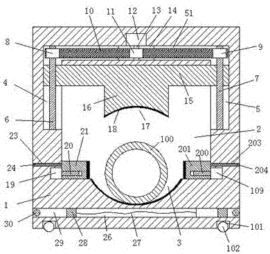
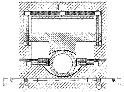
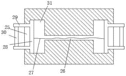
[0020] refer to Figure 1-4 The shown LED energy-saving lamp device includes a frame body 1 and an open cavity 2 arranged in the frame body 1 and passing through front and rear. Rollers 102 are provided in each of the sink chambers 101, so that the four rollers 102 can drive the frame body 1 to move. The top of the left flat wall and the top of the right flat wall of the opening cavity 2 are respectively provided with a left movable slot 4 and a right movable slot 5 correspondingly, and the top flat wall of the opening cavity 2 is provided with a movable slot connecting the left movable slot 4 and the right movable slot. The open slot 51 of the ...


PUM


Abstract

The invention discloses an LED energy-saving lamp device comprising a frame and a front-back-through open cavity which is formed in the frame. The four corners at the bottom of the frame are each provided with a counter cavity. Rolling wheels are arranged in each of the four counter cavities in a rolling mode. The middle of the bottom flat wall of the open cavity is provided with a first semi-open groove. A left movable open groove and a right movable open groove are formed in the top of the left flat wall and the upper portion of the right flat wall top of the open cavity correspondingly and symmetrically. A through groove connecting the left movable open groove and the right movable open groove is formed in the top flat wall of the open cavity. A plate capable of moving up and down is arranged in the open cavity. A convex connecting block is arranged in the middle of the bottom of the plate. The bottom of the convex connecting block is provided with a second semi-open groove. The LED energy-saving lamp device is reasonable in structure, simple to operate, convenient to carry, clamping of a lamp head is safe and stable, the lamp head does not shift, subsequent packaging operation of the lamp head and a lamp tube is convenient, meanwhile, lamp heads of different thicknesses can be clamped, clamping fixing cost of the lamp heads is lowered greatly, packaging efficiency of LED energy-saving lamps is high, and the LED energy-saving lamp device is suitable for use and popularization.

Description

technical field [0001] The invention relates to the technical field of LED energy-saving lamps, in particular to an LED energy-saving lamp device. Background technique [0002] LED energy-saving lamps are widely used due to their low cost, high luminous efficiency, large light-emitting area, no glare, and no ghosting. LED energy-saving lamps are generally packaged by lamp caps and lamp tubes. However, most of the lamp caps are cylindrical structures, which are difficult to fix, and the lamp caps have different sizes and specifications. The general fixing parts can only fix the lamp caps of the same specification when fixing the lamp caps, and cannot meet the requirements of fixing different sizes. Therefore, this greatly reduces the encapsulation work of the lamp cap and the lamp tube, making the encapsulation efficiency low. Therefore, the general fixing parts can no longer meet the requirements of fixing the existing lamp caps of various sizes and specifications. Content...

Claims


Application Information

Patent Timeline
Patent Type & Authority Patents(China)
IPC IPC(8): B25B11/02F21K9/90
CPCB25B11/02F21K9/90
Inventor 俞纯洁
Owner QINGDAO OUSHENG LIGHTING CO LTD
Learn More