Wheel-leg switching mechanism

A technology of wheel legs and shanks, which is applied in the field of mechanism design, can solve the problems of poor road adaptability, slow moving speed, and poor terrain adaptability of walking wheels, and achieve strong road adaptability, reduced driving torque, and strong bearing capacity. Effect

Pending Publication Date: 2017-11-07
LIAONING TECHNICAL UNIVERSITY
View PDF3 Cites 8 Cited by
  • Summary
  • Abstract
  • Description
  • Claims
  • Application Information

AI Technical Summary

Problems solved by technology

[0002] The wheel-shaped structure is suitable for fast movement on flat roads, but its disadvantage is that it has poor terrain adaptability and is difficult to move quickly in rough and complex terrain environments; while the leg-shaped structure has good terrain adaptability and can move in rough terrain environments , but its moving speed is relatively slow
In order to make full use of the advantages of the wheel-shaped structure and the leg-shaped structure, many scholars have designed a variety of wheel-leg structures. The patent application number is 201210244363.0. The wheel-leg structure adds a walking wheel to the end of the leg-shaped structure. The application number is 201410757019.0 The wheel-leg structure published by the patent adds a walking wheel to the middle position of the leg-shaped structure. Both wheel-leg structures add walking wheels on the basis of the leg-shaped structure to realize the transformation of the wheel-leg structure. Due to the limitation of the structure The diameter of the walking wheel is generally small, so the road adaptability of the walking wheel is poor, and obstacles such as large ditches and ridges cannot be passed; the wheel-leg structure published in the patent application number 201410315537.7 adopts the structure in which the wheel is deformed into a leg. The larger diameter of the walking wheel makes it better adaptable to the road surface, but after transforming into a leg-shaped structure, the load on the knee joint is very large, which increases the size of the knee joint structure. In addition, the length of the legs cannot be adjusted by telescopic adjustment, so the length of the legs is relatively short. Less ability to cross obstacles

Method used


Image

  • Wheel-leg switching mechanism
  • Wheel-leg switching mechanism
  • Wheel-leg switching mechanism

Examples


Embodiment

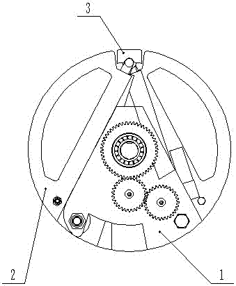
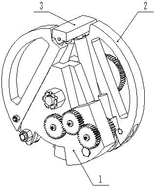
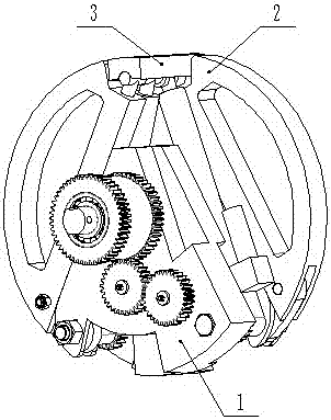
[0016] Examples, see attached Figure 1-9 , a wheel-leg transformation mechanism, comprising a wheel thigh 1, a wheel shank 2 and a wheel foot 3, characterized in that the two wheel shanks 2 are mounted on the wheel thigh 1 through the shank mounting shaft 20, and the wheel foot 3 is passed through the wheel foot pin 23 is installed on a wheel calf 2; the thigh bracket 4 of the wheel thigh 1 is fixedly connected with the wheel leg drive shaft 7 with a key, and is fastened by a nut 13, and the calf expansion drive gear 5 is supported on the wheel leg drive shaft 7 through the bearing 6 On the top, the transmission gear Ⅰ8 and the transmission gear Ⅳ14 are fixedly installed on both ends of the transmission shaft Ⅰ9 through key connection, the transmission shaft Ⅰ9 is installed in the round hole of the thigh support 4, the transmission gear Ⅰ8 meshes with the calf stretching drive gear 5, and the transmission gear Ⅱ11 It is fixedly installed on both ends of the transmission shaft...


PUM


Abstract

The invention discloses a wheel-leg conversion mechanism, which comprises a wheel thigh, a wheel calf and a wheel foot. The wheel calf is installed on the wheel thigh through a calf mounting shaft, and the wheel foot is installed on a wheel calf through a wheel foot pin shaft; the wheel thigh The calf retraction drive gear drives the calf to retract or expand through multi-stage gear transmission to realize the transformation of the wheel shape and the leg shape; the wheel leg drive shaft of the wheel thigh rotates or swings to realize the rolling walking of the wheel-shaped structure or the leg-shaped structure. Gait walking. The wheel-leg conversion mechanism can realize the transformation of the wheel-shaped structure and the leg-shaped structure, and can not only walk quickly on flat roads, but also quickly walk on rough roads. The shape structure has strong bearing capacity, small joint torque, and the length of the wheel legs can be adjusted to allow flexible walking on different road conditions.

Description

technical field [0001] The invention belongs to the field of mechanism design, in particular to a wheel-leg transformation mechanism. Background technique [0002] The wheel-shaped structure is suitable for fast movement on flat roads, but its disadvantage is that it has poor terrain adaptability and is difficult to move quickly in rough and complex terrain environments; while the leg-shaped structure has good terrain adaptability and can move in rough terrain environments , but its movement speed is relatively slow. In order to make full use of the advantages of the wheel-shaped structure and the leg-shaped structure, many scholars have designed a variety of wheel-leg structures. The patent application number is 201210244363.0. The wheel-leg structure adds a walking wheel to the end of the leg-shaped structure. The application number is 201410757019.0 The wheel-leg structure published by the patent adds a walking wheel to the middle position of the leg-shaped structure. Bo...

Claims


Application Information

Patent Timeline
Patent Type & Authority Applications(China)
IPC IPC(8): B62D57/028
CPCB62D57/028
Inventor 魏永乐晁彩霞张兴元吴英彪
Owner LIAONING TECHNICAL UNIVERSITY
Why Eureka
Try Eureka