Petroleum pipeline cleaning device

A technology for oil pipelines and cleaning devices, applied in the directions of cleaning hollow objects, cleaning methods and utensils, chemical instruments and methods, etc., can solve the problems of poor flexibility, weak cleaning strength, poor cleaning effect of cleaning devices, etc. The effect of avoiding cleaning dead corners, improving the load capacity and the ability to overcome obstacles

Inactive Publication Date: 2018-11-02
CHINA UNIV OF PETROLEUM (EAST CHINA)
View PDF7 Cites 11 Cited by
  • Summary
  • Abstract
  • Description
  • Claims
  • Application Information

AI Technical Summary

Problems solved by technology

[0003] In view of this, what this application intends to solve is the technical problem of poor cleaning effect, weak cleaning strength and poor flexibility of the cleaning device in the conventional technology.

Method used


Image

  • Petroleum pipeline cleaning device
  • Petroleum pipeline cleaning device
  • Petroleum pipeline cleaning device

Examples


Embodiment Construction

[0031] The implementation of the present application will be described in detail below with reference to the accompanying drawings and examples, so as to fully understand and implement the implementation process of how the present application uses technical means to solve technical problems and achieve technical effects.

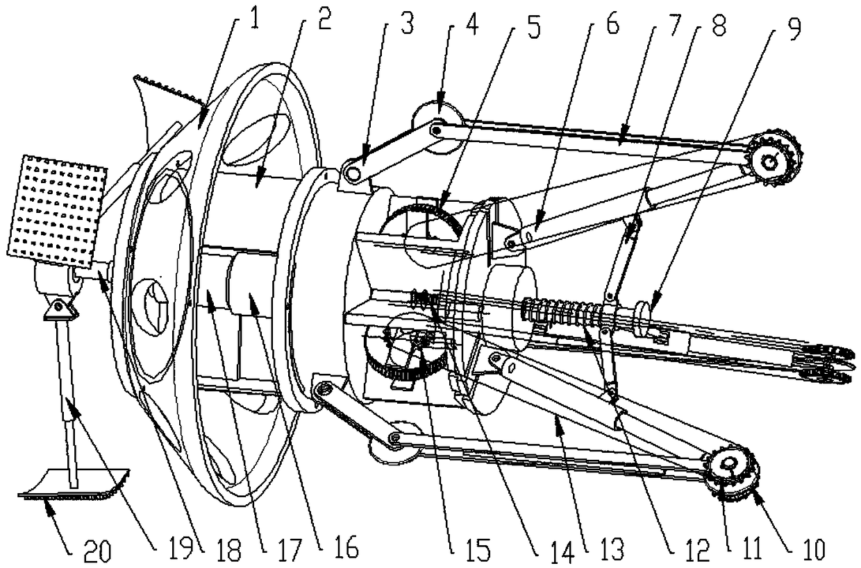
[0032] like figure 1 As shown, a petroleum pipeline cleaning device of the present invention is composed of a driving system, a transmission system, a walking system and a cleaning system, and specifically includes a leather cup 1, a casing 2, a crank 3, a driven traveling wheel 4, a worm wheel 5, and a second compressor Barrel 6, connecting rod 7, adjusting connecting rod 8, adjusting bolt 9, driving wheel 10, driven sprocket 11, adjusting spring 12, chain 13, worm 14, driving sprocket 15, motor 16, reducer 17, Cleaning shaft 18, first compression cylinder rod 19, and cleaning plate 20. The output end of the motor 16 is connected with the worm screw 15, an...


PUM


Abstract

The invention discloses a petroleum pipeline cleaning device which comprises a drive part formed by a motor and a speed reducer, a transmission part formed by a worm wheel-worm, cleaning heads, a packing cup, a shell and the like. Telescopic cylinder rods are arranged at two ends of a cleaner so as to adapt to different pipe diameters. The motor transmits the torque to a worm so as to drive a wormwheel, a chain wheel and a driving walking wheel to move in a pipe, and meanwhile, the torque is transmitted to a cleaning shaft through the speed reducer, so that the aim of cleaning the pipeline isachieved through rotating the cleaning heads. When in work, through the joint action of a triangular support, springs and compression cylinder rods, the tail part of the cleaner can effectively fit to the inner side of the pipeline. When the resistance is too big or the power level is low, air can be pumped into the pipeline, and the cleaner is driven through the trepanned packing cup. The threecleaning heads are arranged at the front end of the cleaner and are connected through connecting buckles, the compression cylinder rods and the cleaning shaft, and the pitching angles of the cleaningheads can be adjusted through the connecting buckles, so that the applicability and the cleaning efficiency of the cleaning device are improved.

Description

technical field [0001] The application belongs to a cleaning device, in particular to an oil pipeline cleaning device. Background technique [0002] The development of the oil and gas industry provides a solid foundation and guarantee for the country's economic construction and people's lives. Oil and gas are the lifeblood of a country's development and an important indicator to measure a country's overall strength, especially its military strength. The oil and gas pipeline is carrying the important mission of safely transporting the country's development momentum. The maintenance and cleaning of the pipeline has played a positive role in prolonging the service life of the pipeline and ensuring the safety of oil and gas gathering and transportation. It is an important guarantee for the development of the oil and gas industry. Oil pipelines need to be cleaned before laying to prevent impurities in oil pipelines from affecting the quality of oil. Traditional oil pipeline clea...

Claims


Application Information

Patent Timeline
Patent Type & Authority Applications(China)
IPC IPC(8): B08B9/051
CPCB08B9/051
Inventor 徐兴平汪海王龙庭张辛刘广斗王言哲王斌
Owner CHINA UNIV OF PETROLEUM (EAST CHINA)
Why Eureka
Try Eureka