Deep ploughing, deep scarification and ridge smashing device

A powder ridge and subsoiling technology, which is applied in the fields of farming machinery, application, agricultural machinery and machinery, etc., can solve the problems of low farming efficiency, incomplete cutting of large pieces of soil, and poor powder ridge effect, so as to improve farming efficiency , increase the crushing effect, and the powder ridge effect is good

Inactive Publication Date: 2015-04-22
GUANGXI WUFENG MACHINERY CO LTD
View PDF4 Cites 12 Cited by
  • Summary
  • Abstract
  • Description
  • Claims
  • Application Information

AI Technical Summary

Problems solved by technology

The current agricultural farming machinery is still lacking in the technology of crushing soil, the effect of powder ridges is not good, and the cutting of large pieces of soil is not thorough, so there are many inconveniences in farming, resulting in low farming efficiency

Method used


Image

  • Deep ploughing, deep scarification and ridge smashing device
  • Deep ploughing, deep scarification and ridge smashing device

Examples


Embodiment 1

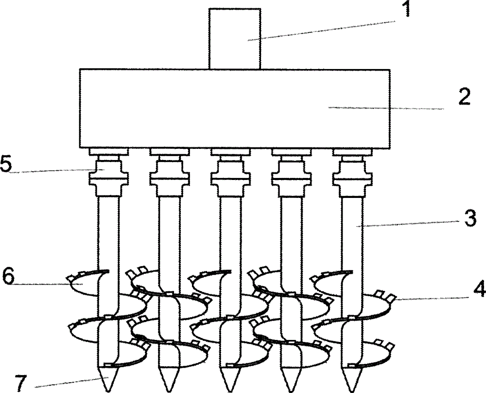
[0019] A deep plowing and loosening powder ridge device, the device includes a hydraulic motor 1, a transmission box 2 and four powder ridge drill bits, the powder ridge drill bit includes a screw shaft 3, a powder ridge knife 4, and the power of the hydraulic motor is transmitted to the powder ridge through the transmission box drill. The top of the screw shaft is provided with a connecting flange 5, a screw blade 6, and a drill tip 7; the screw blade 6 is installed on the screw shaft 3, and the outer edge of the screw blade is provided with a powder ridge knife 4, and the spiral shaft centers of two adjacent powder ridge drill bits The distance is 40cm, the radius of the spiral shaft is 4cm, the vertical distance from the powder ridge cutter head to the edge of the spiral leaf is 6cm, the radius of the spiral blade is 20cm, and the two powder ridge drill bits alternately rotate.

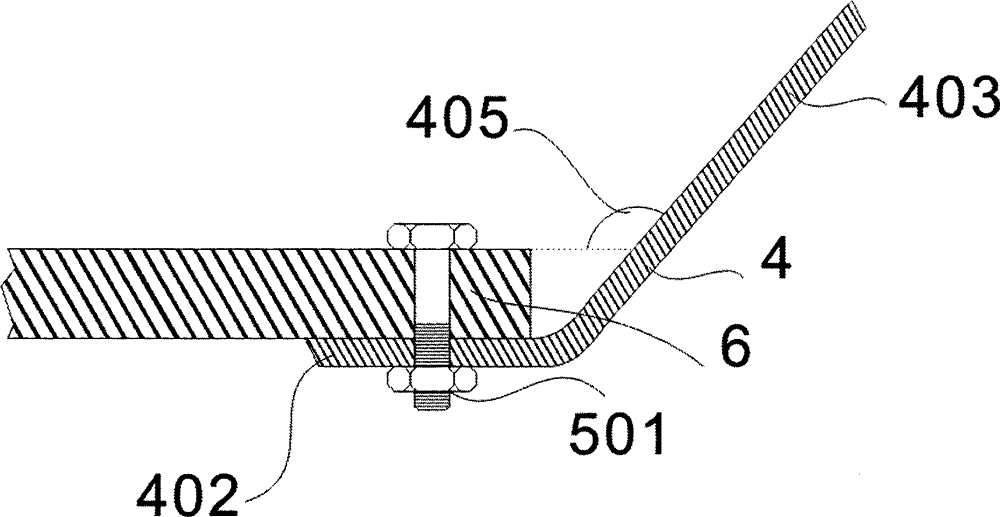
[0020] The powder ridge cutter 4 is composed of a connecting portion 402 and a cutter portion 4...

Embodiment 2

[0022] A deep plowing and loosening powder ridge device, the device includes an electric motor 1, a transmission box 2 and four powder ridge drill bits, the powder ridge drill bit includes a screw shaft 3, a powder ridge knife 4, and the power of the hydraulic motor is transmitted to the powder ridge through the transmission box drill. The top of the screw shaft is provided with a connecting flange 5, a screw blade 6, and a drill tip 7; the screw blade 6 is installed on the screw shaft 3, and the outer edge of the screw blade is provided with a powder ridge knife 4, and the spiral shaft centers of two adjacent powder ridge drill bits The distance is 50cm, the radius of the spiral shaft is 4cm, the vertical distance from the powder ridge cutter head to the edge of the spiral leaf is 6cm, the radius of the spiral blade is 16cm, and the two powder ridge drill bits alternately rotate.

[0023] The powder ridge cutter 4 is composed of a connection part 402 and a cutter part 403, wh...


PUM


Abstract

The invention discloses a deep ploughing, deep scarification and ridge smashing device. The device comprises a motor 1, a transmission case 2 and at least two ridge smashing drill bits. Each ridge smashing drill bit comprises a screw shaft 3, ridge smashing cutters 4, a connecting flange 5 arranged on the top of the screw shaft, a screw blade 6 and a drill tip 7. Each screw blade 6 is mounted on the corresponding screw shaft 3, and the ridge smashing cutters 4 are arranged on the outer edge of each screw blade. The deep ploughing, deep scarification and ridge smashing device is characterized in that the distance from ridge smashing cutter heads of the ridge smashing mechanism to the screw shafts is larger than half the distance between the external diameter parts of every two adjacent screw shafts and smaller than the distance between the external diameter parts of every two adjacent screw shafts. The deep ploughing, deep scarification and ridge smashing device solves the problems that a ridge smashing machine in the prior art is not thorough in cutting of large soil blocks and bad in ridge smashing effect, tillage efficiency is improved, and the application and popularization economic benefits and social benefits are very obvious.

Description

technical field [0001] The invention relates to an agricultural machine, in particular to a device for deep plowing and loosening powder ridges. Background technique [0002] The powder ridge machine is a new type of high-efficiency farming machine for dry land. According to the planting needs of different crops, one or more auger-shaped machines are used to grind the soil vertically at one time and suspend it naturally into ridges for planting on the ridge surface. related crops. The current agricultural farming machinery is still lacking in soil breaking technology, the effect of powder ridges is not good, and the cutting of large pieces of soil is not thorough, so there are many inconveniences in farming, resulting in low farming efficiency. Contents of the invention [0003] The technical problem to be solved by the invention is to provide a device for deep plowing and loosening powder ridges, which can quickly and thoroughly cut the soil and improve the farming effic...

Claims


Application Information

Patent Timeline
Patent Type & Authority Applications(China)
IPC IPC(8): A01B33/06A01B33/10
Inventor 李阳铭
Owner GUANGXI WUFENG MACHINERY CO LTD
Why Eureka
Try Eureka