
Full-automatic fracture steel plate model personalized reconstruction method

A fully automatic, model-based technology, applied in 3D modeling, image data processing, special data processing applications, etc., can solve problems such as excessive bleeding, poor robustness, and inability to achieve automatic segmentation

Active Publication Date: 2017-11-07
DALIAN UNIV OF TECH
View PDF3 Cites 14 Cited by
  • Summary
  • Abstract
  • Description
  • Claims
  • Application Information

AI Technical Summary

Problems solved by technology

[0002] At present, the combination of artificial reduction and internal fixation of the injured limb is generally used in fracture surgery. The problems of this method are large trauma, heavy bleeding, and easy to cause complications such as neurovascular injury.
[0004] The method of section segmentation based on the angle between the section normal vector and the axis is poor in robustness, and cannot be well segmented when encountering a section with a complex structure, and manual selection is required, and automatic segmentation cannot be achieved
[0005] Simply aligning the main axis of the broken bone cannot meet the requirements of pre-registration, and the cross-sectional direction of the broken bone may deviate from each other, and the cross-sectional shape cannot be roughly consistent, which can easily lead to inaccurate fine registration

Method used


Image

  • Full-automatic fracture steel plate model personalized reconstruction method
  • Full-automatic fracture steel plate model personalized reconstruction method
  • Full-automatic fracture steel plate model personalized reconstruction method

Examples


Embodiment Construction

[0119] In order to make the purpose, technical solutions and advantages of the embodiments of the present invention more clear, the technical solutions in the embodiments of the present invention are clearly and completely described below in conjunction with the drawings in the embodiments of the present invention:

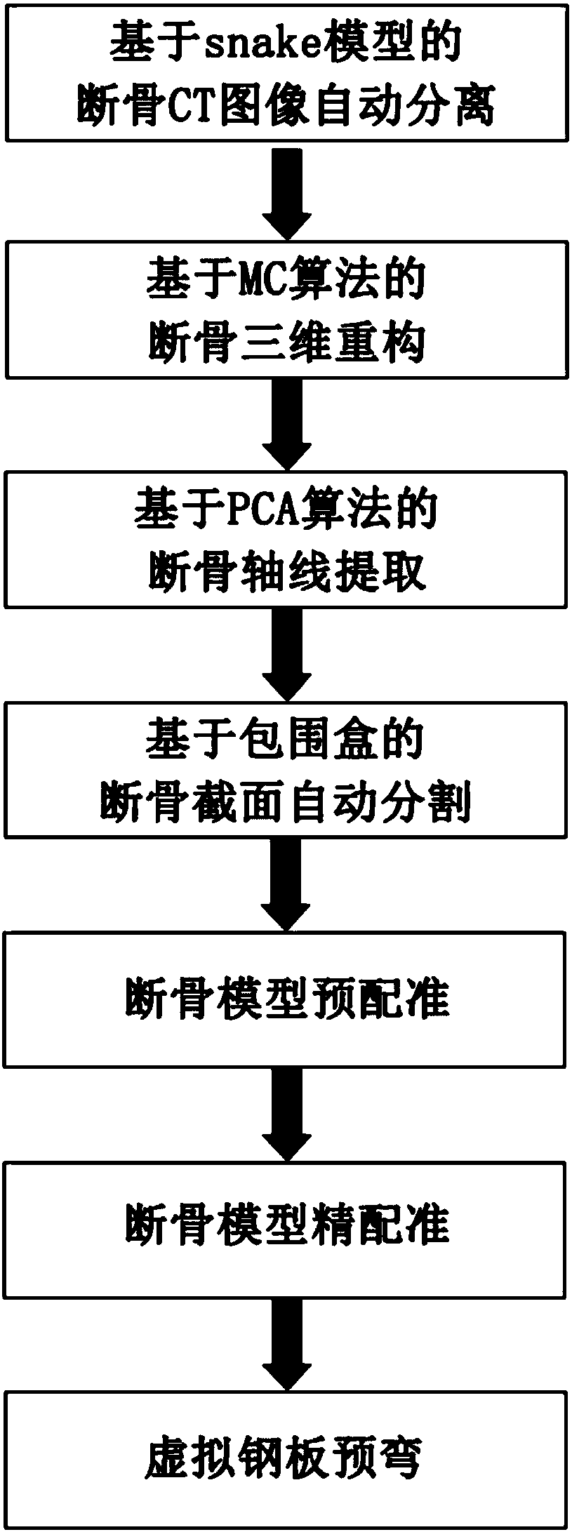
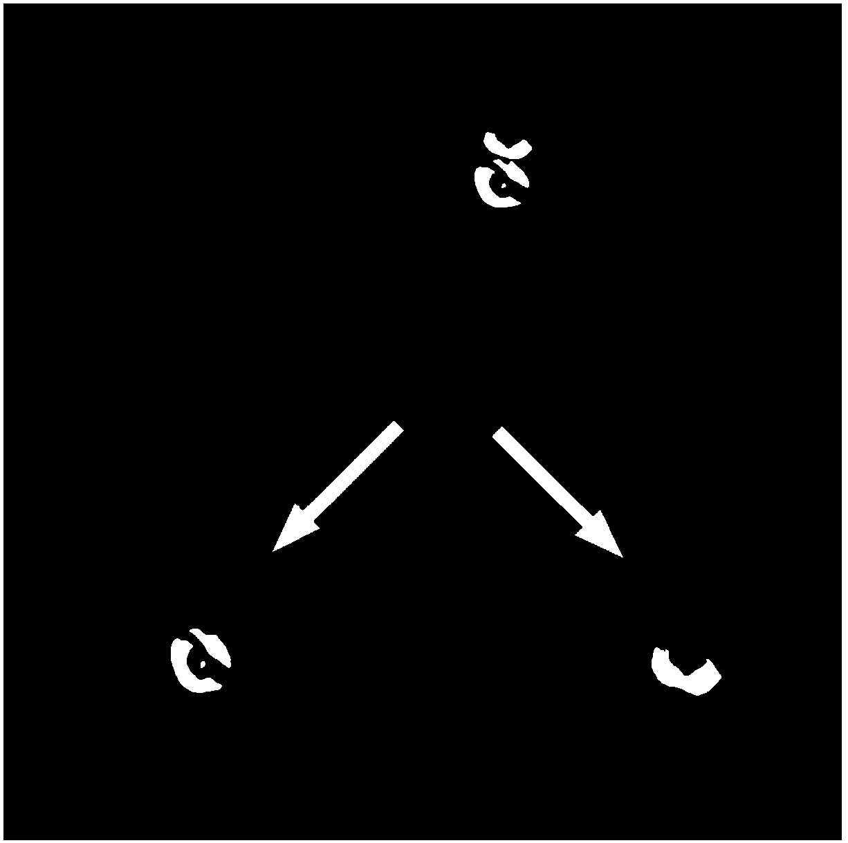
[0120] Such as Figure 1-17 Shown: Fully automatic fracture plate model personalized reconstruction method This method is based on the snake model for automatic separation of CT images of broken bones. The separation effect is as figure 2 shown.

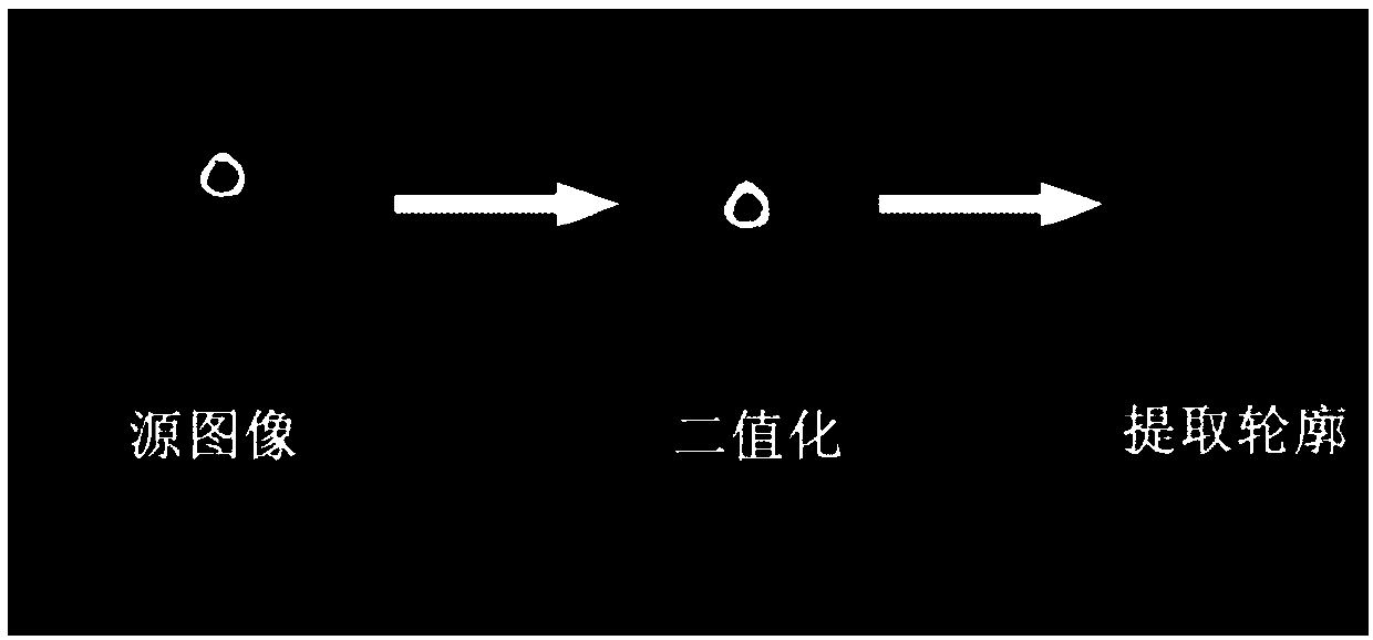
[0121] Binary image. The imported CT image is a grayscale image. Set a threshold T. The grayscale value of pixels greater than T is set to 255, and the grayscale value of pixels less than or equal to T is set to 0. After a lot of experiments, the best effect is when the value of T is 130. , the effect of binarization is as image 3 .

[0122] Extract contours. There are two advantages of contour extraction before ...


PUM


Abstract

The invention discloses a full-automatic fracture steel plate model personalized reconstruction method. The method comprises the following steps of broken bone image separation; broken bone three-dimensional reconstruction; broken bone axis extraction, wherein an initial sample matrix Z of three-dimensional models of a first broken bone and a second broken bone is generated, the sample matrix is subjected to centralization to obtain a matrix X, characteristic values of a covariance matrix C and a covariance matrix C of the matrix X are calculated, and characteristic vectors corresponding to the maximum characteristic values are selected as broken bone axes of the first broken bone and the second broken bone; broken bone section segmentation, wherein characteristic points are extracted from the three-dimensional models of the first broken bone and the second broken bone, the characteristic points are divided into the head part and the tail part according to a length buffer value and a mesh model, and four sets of head and tail characteristic points of the first broken bone and the second broken bone are formed separately; broken bone registration; virtual steel plate pre-bending, wherein point selection is conducted on spliced broken bone fracture surface attachments, and the size and shape of the steel plate model are determined; a normal vector value of each triangular patch is calculated, thickening is conducted on each plane to a certain extent according to the normal vector direction, the gaps are filled up, and finally the simulated steel plate three-dimensional data is obtained.

Description

technical field [0001] The invention relates to a fully automatic fracture plate model personalized reconstruction method. Involves patent classification number G06 Calculation; Calculation; Counting G06T General image data processing or generation G06T7 / 00 Image analysis, for example from bitmap to non-bitimage. Background technique [0002] At present, the combination of artificial reduction and internal fixation of the injured limb is generally used in fracture surgery. The problems of this method are large trauma, heavy bleeding, and easy to cause complications such as neurovascular injury. Therefore, we can use the computer to carry out virtual splicing of the broken bone model, so that various geometric parameters of the steel plate can be obtained before the operation. However, there are many problems in the current virtual stitching method of broken bones, such as inaccurate section segmentation and inaccurate pre-registration, which greatly affect the accuracy of b...

Claims


Application Information

Patent Timeline
Patent Type & Authority Applications(China)
IPC IPC(8): G06F19/00G06T17/00
CPCG06T17/00
Inventor 刘斌张松刘文鹏王明哲张晓慧杨乙乾
Owner DALIAN UNIV OF TECH
Learn More