
Small-size self-locking explosion-proof connector used for power cable wiring and installation method thereof
A technology for power cables and connectors, applied in the field of small explosion-proof connectors, can solve problems such as difficulty in ensuring construction quality, incomplete filling, and long curing time for silicone
- Summary
- Abstract
- Description
- Claims
- Application Information
AI Technical Summary
Problems solved by technology
Method used
Image

Examples
Embodiment Construction
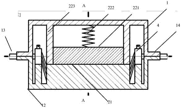
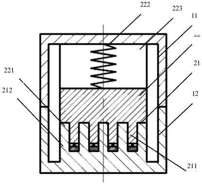
[0036] Figure 1-3 The structure of the self-locking explosion-proof connector of the present invention is schematically shown, and the explosion-proof connector includes a connector housing 1 , a connecting device 2 , a sealing device 3 , and a wire pressing device 4 .
[0037] The connector housing 1 is a square tubular body with a stepped inner hole, and is composed of two parts, an upper shell 11 and a lower shell 12 . The upper casing 11 and the lower casing 12 are provided with self-locking bayonet openings, and the self-locking bayonet openings may be of a known structure (not shown in the figure). A gasket (not shown in the figure) is arranged between the upper casing 11 and the lower casing 12 to ensure the sealing between the upper and lower casings. Both ends of the housing 1 have an inlet end 13 and an outlet end 14 of the cable.
[0038] The connecting device 2 is arranged inside the housing 1 and includes a cable penetrating device 21 and a cable pressing devic...
PUM
| Property | Measurement | Unit |
|---|---|---|
| Wire diameter | aaaaa | aaaaa |
Abstract
Description
Claims
Application Information