Energy storage device based on friction power generator
A technology of friction generator and energy storage device, applied in the direction of friction generator, electric energy storage system, electrical components, etc., can solve the problems of low utilization rate and large loss, and achieve the effect of avoiding a large amount of loss
- Summary
- Abstract
- Description
- Claims
- Application Information
AI Technical Summary
Problems solved by technology
Method used
Image

Examples
Embodiment 1
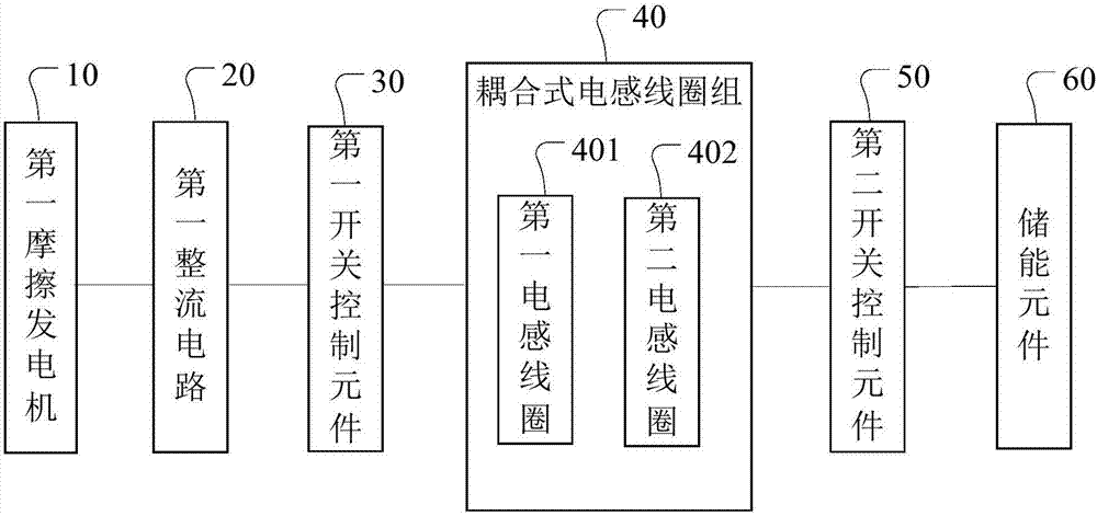
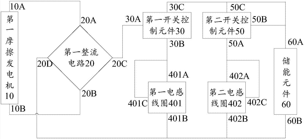
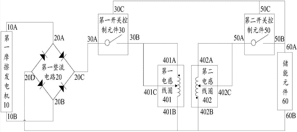
[0022] Figure 2a and Figure 2b A structural diagram of an energy storage device based on a friction generator provided by Embodiment 1 of the present invention is shown. in, Figure 2a shows the modular structure diagram, Figure 2b A structural diagram represented by electronic components is shown. The energy storage device includes: a first friction generator 10 , a first rectifier circuit 20 , a first switch control element 30 , a first inductance coil 401 , a second inductance coil 402 , a second switch control element 50 and an energy storage element 60 .
[0023] The circuit connection relationship between each of the above parts is introduced in detail below:
[0024] Such as Figure 2a and Figure 2b As shown, the first friction generator 10 includes two ends, respectively a first end 10A and a second end 10B. The first rectifier circuit 20 includes four terminals, namely a first terminal 20A, a second terminal 20B, a third terminal 20C and a fourth terminal 2...
Embodiment 2
[0058] Figure 4 A structural diagram of an energy storage device based on a friction generator provided by Embodiment 2 of the present invention is shown. The energy storage device includes: a first friction generator 10 , a first rectifier circuit 20 , a first switch control element 30 , a first inductance coil 401 , a second inductance coil 402 , a second switch control element 50 and an energy storage element 60 . The main difference between the second embodiment and the first embodiment is that the first inductance coil 401 and the second inductance coil 402 are both multi-tap coils, and each tap corresponds to a different number of coil turns. Correspondingly, the first switch control element 30 further includes: a plurality of switches, each switch is respectively connected to a tap in the first inductance coil 401, and the first switch control element 30 controls the first switch by controlling the on-off of the plurality of switches. The rectifier circuit 20 is conne...
Embodiment 3
[0079] Figure 5 It shows a structural diagram of an energy storage device based on a friction generator provided by Embodiment 3 of the present invention, as shown in Figure 5 As shown, the energy storage device includes: a first friction generator 10, a first rectifier circuit 20, a first switch control element 30, a first inductance coil 401, a second inductance coil 402, a second switch control element 50, an energy storage The element 60 , the second friction generator 70 and the second rectification circuit 80 . It can be seen that, on the basis of Embodiment 1, Embodiment 3 further adds a second friction generator 70 and a second rectifier module 80. In addition, the rest of Embodiment 3 is the same as Embodiment 1. The following Only the different parts of the third embodiment and the first embodiment are described, and the same parts are not repeated here.
[0080] Wherein, the second friction generator 70 includes two ends, respectively a first end 70A and a secon...
PUM
 Abstract
Description
Claims
Application Information