Monitoring equipment used for bridge

A technology for monitoring equipment and bridges, applied in the parts of color TVs, parts of TV systems, TVs, etc., can solve the problems of increased difficulty in installation or maintenance, unsuitable for promotion and use, complicated installation and use, etc., to reduce labor labor, increased installation and maintenance speed, and the effect of easy maintenance and installation

Inactive Publication Date: 2017-11-07
沈春慧
View PDF0 Cites 2 Cited by
  • Summary
  • Abstract
  • Description
  • Claims
  • Application Information

AI Technical Summary

Problems solved by technology

[0002] At present, on some bridges, monitoring equipment for monitoring and photographing illegal vehicles can often be seen. However, when installing these monitoring equipment, the monitoring angle must first be adjusted and then fixed on the support rod through a spiral structure. The operation is too complicated and If the monitoring angle is adjusted in the later stage, it needs to be disassembled, readjusted and finally fixed. The process is cumbersome, time-consuming and labor-intensive. At the same time, because the support frame of the monitoring equipment often has a certain height, it makes installation or maintenance more difficult. In the prior art, there are many monitoring devices that can adjust the angle by themselves, but they are expensive and complicated to install and use, so they are not suitable for popularization and use.

Method used


Image

  • Monitoring equipment used for bridge
  • Monitoring equipment used for bridge
  • Monitoring equipment used for bridge

Examples


Embodiment Construction

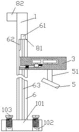
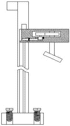
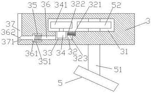
[0018] Such as Figure 1-Figure 5 As shown, a monitoring device for a bridge of the present invention includes a pillar and a frame 3 that slides and fits with the pillar 1. The bottom end of the pillar 1 is provided with a fixed seat 101, and the fixed seat 101 four A fixing hole 102 is provided in each corner, and a fixing bolt 103 is arranged in the fixing hole 102. A sliding chamber 6 is arranged on the right side of the pillar 1, and a screw rod 63 is arranged in the sliding chamber 6. The screw rod The top of 63 is rotationally connected with the first driving machine 61, and the top center of the inner wall on the left side of the slide chamber 6 is fixed with an insert 62 with a beveled portion 621, and the frame 3 is arranged in the slide chamber 6 and Sliding fit, the frame 3 is helically connected with the screw rod 63, and the top center of the left end surface of the frame 3 is provided with an insert with an oblique groove 371 for matching with the insert block 6...


PUM


Abstract

The invention discloses monitoring equipment used for a bridge. The monitoring equipment comprises a strut and a frame connected to the strut in a sliding and matching manner, wherein a fixed seat is arranged at the bottom end of the strut; fixing holes are arranged in four corners of the fixed seat; fixed bolts are arranged in the fixing holes; a slide cavity is arranged at the right side in the strut; a screw rod is arranged in the slide cavity; the top end of the screw rod is rotatably connected to a first driver; an insertion block with an oblique angle part is fixedly arranged at the center of the top end of the inner wall at the left side of the slide cavity; the frame is arranged in the slide cavity in a sliding and matching manner; the frame is connected to the screw rod in a matching manner through a screw thread; a slot with an oblique angle groove is arranged at the center of the top end of the end face at the left side of the frame; a control cavity is arranged at the center in the frame; a rotating shaft is arranged at the right side in the control cavity; the lower end of the rotating shaft penetrates through the frame and extends downwards and is connected to the frame in a rotating and matching manner; and the lower end of the rotating shaft is obliquely and fixedly connected to a monitoring probe. The monitoring equipment has simple structure and easy operation, the manual labor force is reduced and the service efficiency is improved.

Description

technical field [0001] The invention relates to the field of bridge monitoring, in particular to monitoring equipment for bridges. Background technique [0002] At present, on some bridges, monitoring equipment for monitoring and photographing illegal vehicles can often be seen. However, when installing these monitoring equipment, the monitoring angle must first be adjusted and then fixed on the support rod through a spiral structure. The operation is too complicated and If the monitoring angle is adjusted in the later stage, it needs to be disassembled, readjusted and finally fixed. The process is cumbersome, time-consuming and labor-intensive. At the same time, because the support frame of the monitoring equipment often has a certain height, it makes installation or maintenance more difficult. In the prior art, there are also more monitoring devices that can adjust the angle by themselves, but they are expensive, complicated to install and use, and are not suitable for pop...

Claims


Application Information

Patent Timeline
Patent Type & Authority Applications(China)
IPC IPC(8): H04N5/232
CPCH04N23/60
Inventor 沈春慧
Owner 沈春慧
Why Eureka
Try Eureka