Control table with movable table surface

A technology for consoles and countertops, which is applied in the direction of electrical equipment shells/cabinets/drawers, casings/cabinets/drawer parts, electrical components, etc., and can solve the problem of limited area, inconvenient operation of the console, and the occupation of the table by the threading hole Space and other issues, to achieve the effect of simple and beautiful overall shape, convenient operation and convenient connection

Pending Publication Date: 2017-11-07
固安飞马拓新电子设备有限公司
View PDF7 Cites 0 Cited by
  • Summary
  • Abstract
  • Description
  • Claims
  • Application Information

AI Technical Summary

Problems solved by technology

[0003] In the current consoles on the market, the countertop components are routed into the console, generally follow the instructions of opening holes on the console countertop and using wire hole brushes and other accessories. After the countertop component cables pass through the threading holes, personnel connect and manage the cables inside the chassis below the countertop. Due to the limitation of the height of the table, the operator usually needs to lean over to operate, which is very inconvenient; due to the limited area of ​​the table, the threading hole needs to occupy a certain amount of space on the table, and there are often devices placed around the threading hole. When threading or When changing the line, it is necessary to clean the devices around the threading hole before the operation can be performed, which is inconvenient

Method used


Image

  • Control table with movable table surface
  • Control table with movable table surface
  • Control table with movable table surface

Examples


Embodiment Construction

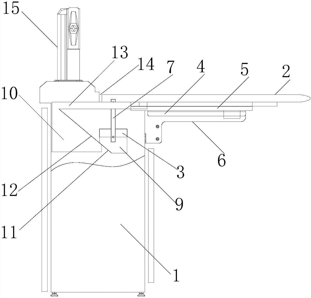
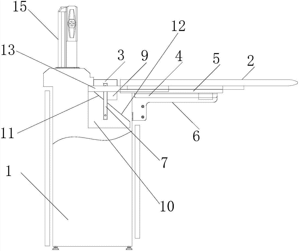
[0018] like figure 1 , 2 As shown, the present invention provides a console with a movable table top. A table top 2 is arranged on the base 1. A distance 14 is set between the closed state of the table top 2 and the edge of the base. The base 1 is provided with a wiring board 3 near the movable table top; The use direction of the tabletop 2 is provided with a pair of first slide rails 4 in the horizontal direction.

[0019] In order to make the setting of the first sliding rail 4 more stable, a preferred technical solution is that the surface of the base 1 opposite to the wiring board 3 is vertically provided with a fixing member 6 , and the first sliding rail 4 is arranged on the fixing member 6 .

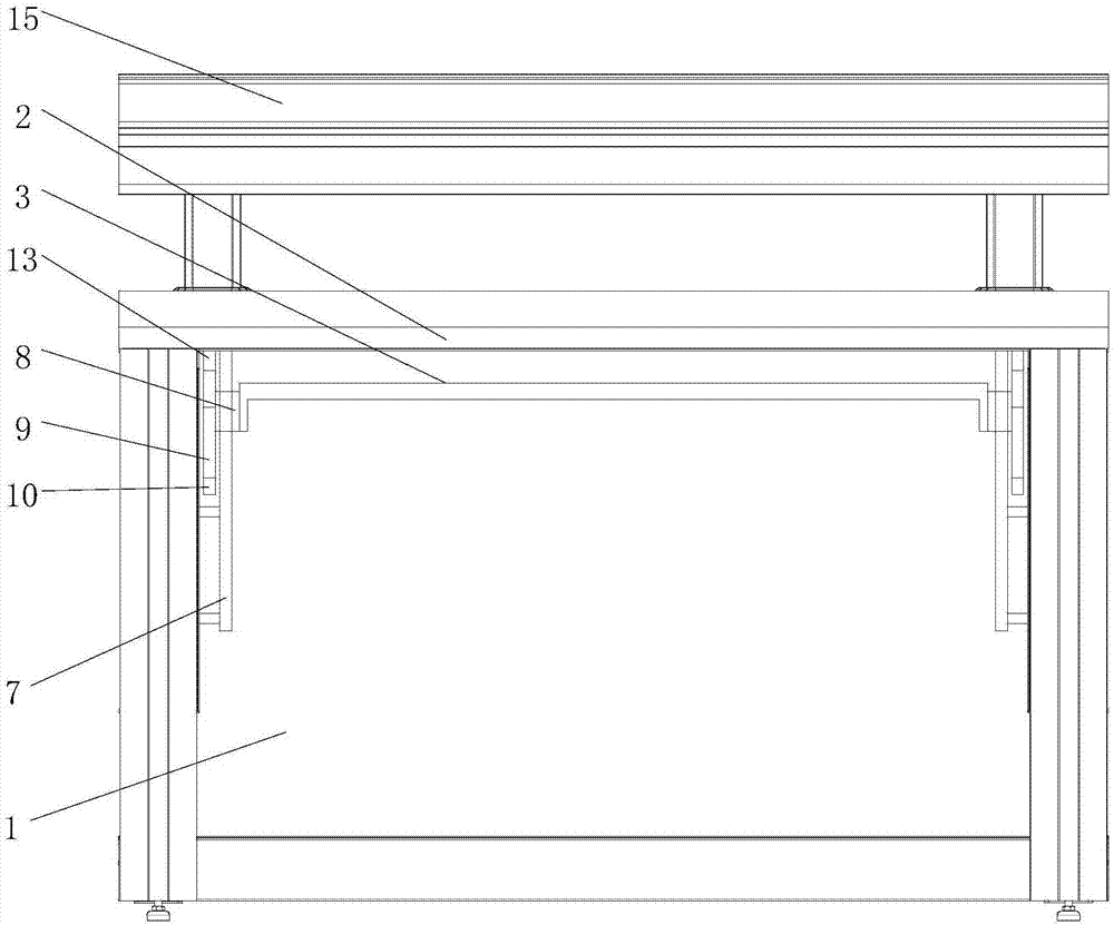
[0020] like figure 1 , 2 , 3, and 4, in order to open the table top 2, it is more simple and convenient to raise the terminal board 3 upwards, reduce the operation steps, make the terminal board 3 rise without other auxiliary tools to fix it, and drive the table top 2 to the le...


PUM


Abstract

The invention belongs to the field of intelligent office furniture and particularly relates to a control table with a movable table surface. The control table with the movable table surface comprises a base arranged on the ground and the movable table surface arranged on the base, wherein the side, close to the movable table surface, inside the base is provided with a wiring board; two side walls inside the base are provided with a pair of second sliding rails in a vertical direction; each second sliding rail is provided with a second sliding block capable of moving along the rail direction of the second sliding rail; two ends of the wiring board are fixed on the pair of second sliding blocks; a pair of first sliding rails in a horizontal direction is arranged on the base in a front-rear mode along the table surface using direction; each first sliding rail is provided with a first sliding block capable of moving along the rail direction of the first sliding rail; the bottom part of the table surface is connected with the first sliding block; the wiring board is driven to move along the second sliding rail direction through a linkage mechanism; the wiring board is exposed; connection of a cable is facilitated; and a proper gap is left between the table surface and the base to enable the cable to pass through. The whole shape of the control table is more concise and attractive, and the table surface is complete.

Description

technical field [0001] The invention belongs to the field of intelligent office furniture, and in particular relates to a console with a movable table top. Background technique [0002] With the advancement of science and technology and the improvement of people's living standards, office furniture is gradually developing in the direction of intelligence and humanization. [0003] In the current consoles on the market, the countertop components are routed into the console, generally follow the instructions of opening holes on the console countertop and using wire hole brushes and other accessories. After the countertop component cables pass through the threading holes, personnel connect and manage the cables inside the chassis below the countertop. Due to the limitation of the height of the table, the operator usually needs to lean over to operate, which is very inconvenient; due to the limited area of ​​the table, the threading hole needs to occupy a certain amount of space...

Claims


Application Information

Patent Timeline
IPC IPC(8): H05K5/02
CPCH05K5/0217H05K5/0234
Inventor 刘杰陈少淮余有田于滨
Owner 固安飞马拓新电子设备有限公司
Why Eureka
Try Eureka