A track changing vehicle

A technology for working vehicles and rails, which is applied in the directions of track, track laying, track maintenance, etc. It can solve problems such as rail invasion, hidden dangers of train operation safety, long rail movement, etc., to reduce stress, save time for unloading new rails, reduce The effect of the time of collision and up-track

Active Publication Date: 2020-02-07
ZHUZHOU TIMES ELECTRONICS TECH CO LTD +1
View PDF6 Cites 0 Cited by
  • Summary
  • Abstract
  • Description
  • Claims
  • Application Information

AI Technical Summary

Problems solved by technology

This way of changing rails needs to place new rails in advance. Changes in the on-site rail temperature will cause the long rails to move due to rail rise, resulting in rail intrusion, which brings safety hazards to the operation of trains on the line. No matter where the old rails are replaced The same problem will occur on the outside of the sleeper or the center of the road

Method used


Image

  • A track changing vehicle
  • A track changing vehicle
  • A track changing vehicle

Examples


Embodiment 1

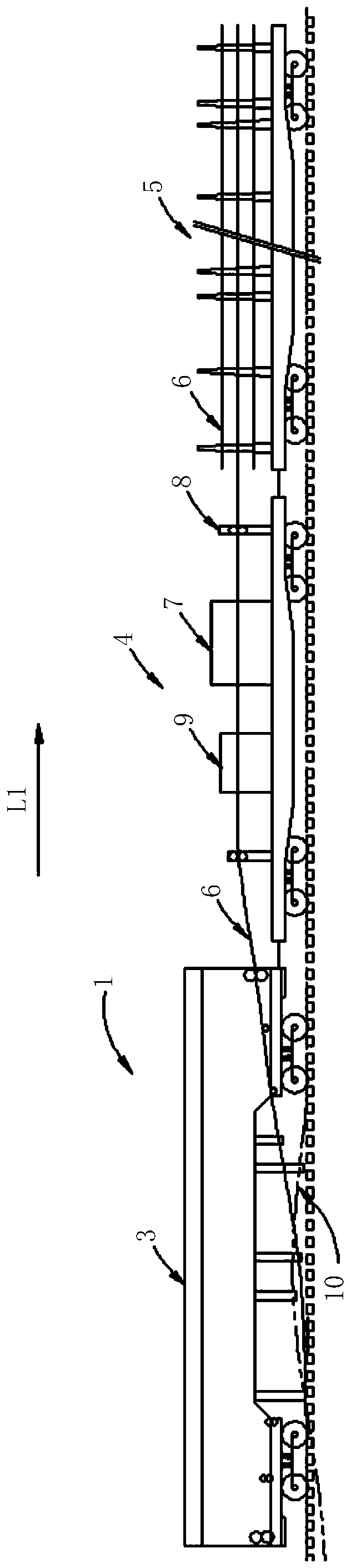
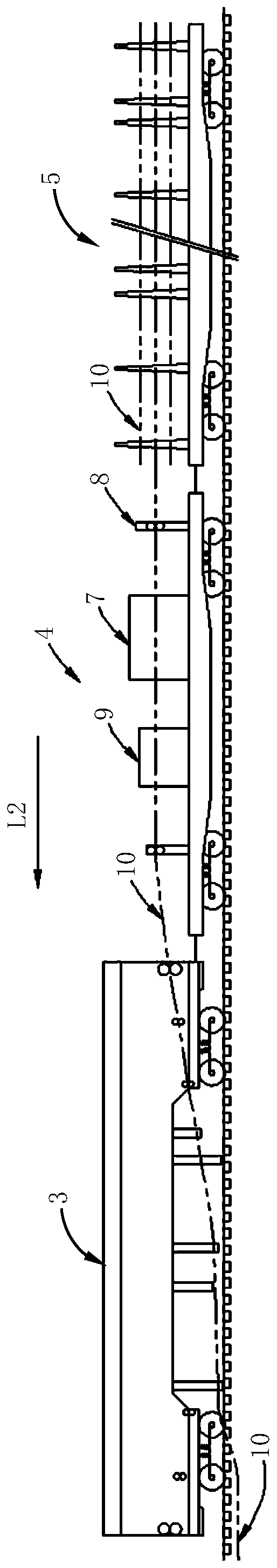
[0039] as attached figure 1 And attached figure 2 As shown, a specific embodiment of a rail changing operation vehicle. The rail changing operation vehicle 1 includes: a replacement module 3 , a loading and unloading module 4 and a transportation module 5 which are sequentially connected along the construction work direction. When changing the new rail 6, the operation direction of the rail change vehicle 1 is as attached figure 1 Shown in the middle arrow L1, the operation direction of the rail change vehicle 1 when reclaiming the old rail 10 is as attached figure 2 Indicated by the middle arrow L2. in:

[0040] The transport module 5 loads and transports the new rail 6 .

[0041] The loading and unloading module 4 is provided with a rail transfer device 7 , and the rail transfer device 7 transfers the new rail 6 to the replacement module 3 .

[0042] The loading and unloading module 4 is provided with a rail splitting device 8, and the rail splitting device 8 adjusts ...

Embodiment 2

[0059] In this embodiment, the rail change vehicle 1 also includes a rail welding module 2 connected to the replacement module 3 and capable of operating independently for welding the new rails 6 adjacent to each other on the line. The rail welding module 2 has a self-propelled power. When the rail changing vehicle 1 reaches the construction starting point within the skylight time, the rail welding module 2 is unlocked and decoupled from the rail changing vehicle 1 . After the replacement module 3 unloads the new rail 6 delivered into the sinker groove of the sleeper, the rail welding module 2 welds the new rails 6 adjacent to each other on the line. as attached Figure 5 As shown, the rail changing operation vehicle 1 includes: a welding rail module 2, a replacement module 3, a loading and unloading module 4 and a transport module 5, which are sequentially connected along the construction operation direction, and the operation method includes the following steps:

[0060] S...

Embodiment 3

[0068] In this embodiment, the rail changing operation vehicle 1 also includes a dismantling module 11 connected between the replacement module 3 and the loading and unloading module 4. After the rail dividing device 8 adjusts the new rails 6 transferred to a suitable distance, the dismantling module 11 Remove the remaining fasteners from the line. as attached Image 6 As shown, the track changing operation vehicle 1 includes: a replacement module 3, a disassembly module 11, a loading and unloading module 4 and a transport module 5, which are sequentially connected along the construction operation direction, and the operation method includes the following steps:

[0069] S11: After the rail fasteners are disassembled according to the mode of tightening 1 loosening 8, the rail change vehicle 1 arrives at the construction starting point within the skylight time, and the new rail 6 is loaded and transported by the transport module 5;

[0070] S12: The rail transfer device 7 arra...


PUM


Abstract

The invention discloses a rail replacing work vehicle. The rail replacing work vehicle comprises a replacement module, a loading and unloading module and a transporting module which are sequentially connected in the construction operation direction. The transporting module is used for achieving loading transporting on a new steel rail. The loading and unloading module is provided with a steel rail conveying device, and the new steel rail is conveyed to the replacement module through the steel rail conveying device. A rail dividing device is arranged on the loading and unloading module, the conveyed new steel rail is adjusted to form appropriate gap through the rail dividing device. An old steel rail is carried away from a rail sinking groove of a sleeper through the replacement module, and the new steel rail conveyed through the steel rail conveying device is unloaded into the rail sinking groove of the sleeper. By means of the rail replacing work vehicle, all work including rail unloading, rail replacing and rail receiving is completed within one skylight point, the new rail replacing time of a traditional rail replacing construction manner is saved, and potential safety hazards in the rail replacing construction operation are effectively avoided.

Description

technical field [0001] The invention relates to the field of railway engineering operations, in particular to a rail-changing operation vehicle with the function of continuous and rapid rail-changing operations applied in the field of railway engineering operations and maintenance. Background technique [0002] In the field of railway engineering, railway rails need to be replaced in time when they reach a certain life span. At present, railway rail replacement operations mainly use manual or mechanical rail replacement in the skylight point. The manual rail change method requires a large number of construction workers, low operating efficiency, high labor intensity, and is prone to safety accidents. It has been used less and less in overhaul construction. The mechanical rail change is to use the rail change equipment or the rail change car to replace the rail. The rail change method is basically the same, but all the work of unloading, welding, changing and closing can not ...

Claims


Application Information

Patent Timeline
Patent Type & Authority Patents(China)
IPC IPC(8): E01B29/16
CPCE01B29/16E01B2203/017
Inventor 李石平杨国涛向涌王琰刘莎
Owner ZHUZHOU TIMES ELECTRONICS TECH CO LTD
Why Eureka
Try Eureka