High dynamic imaging module based on DMD dynamic beam splitting

An imaging module, high dynamic technology, applied in image communication, components of color TV, components of TV system, etc., can solve the problem of lack of large-scale system-level design and application ability, achieve large imaging dynamic range ability, realize exposure Quantity and quality assurance

Active Publication Date: 2017-11-10
NAT UNIV OF DEFENSE TECH
View PDF5 Cites 25 Cited by
  • Summary
  • Abstract
  • Description
  • Claims
  • Application Information

AI Technical Summary

Benefits of technology

This patented method allows for better capturing of images that have varying levels of brightness (light). It uses multiple cameras together to cover wider ranges while still maintain good resolution. By combining these techniques into one machine, this technique improves performance over previous methods but also provides higher versatility compared to current systems. Overall, this process ensures complete visual analysis across all aspects of the subject being captured simultaneously without sacrificing accuracy due to limited sensor capabilities.

Problems solved by technology

This patented problem addressed in this patents relates to improving the performance of multiplexed imagers during fast motion changes without sacrificially overloading any important parts due to insufficient exposures caused by limited depth ranges. Current techniques involve either increasing sensitivity levels or reducing exposure intensities altogether, resulting in poorer overall visual experiences when analyzing highly dynamic environments like firing range photography.

Method used


Image

  • High dynamic imaging module based on DMD dynamic beam splitting
  • High dynamic imaging module based on DMD dynamic beam splitting
  • High dynamic imaging module based on DMD dynamic beam splitting

Examples


Embodiment Construction

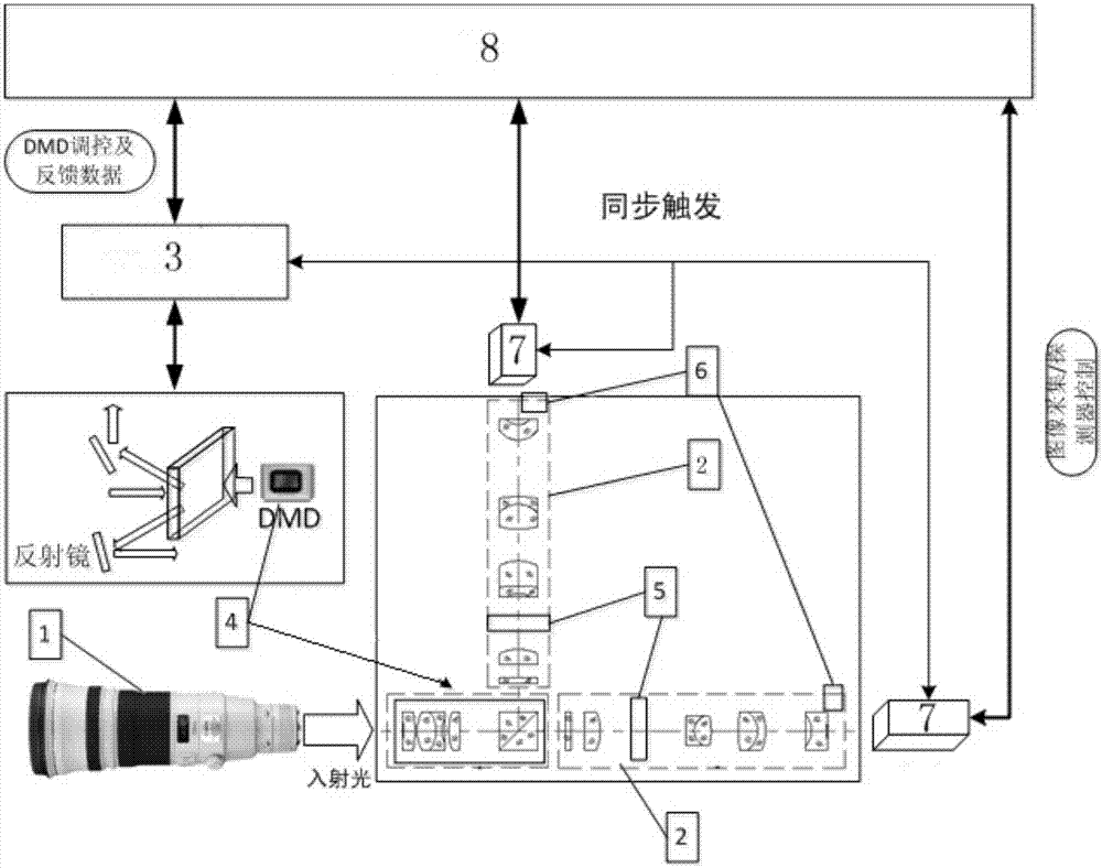
[0029] The structure of the high dynamic imaging module of DMD dynamic spectroscopy is as follows figure 1 Shown. The system includes the main mirror 1, the adapter 2, the DMD spatial light modulator 3, the dynamic beam splitting device 4, the light intensity dynamic adjustable mechanism 5, the position sensor 6, the camera 7, the computer 8,

[0030] 1. Hardware composition and basic principles

[0031] The basic principle of the system is, such as figure 1 When the system shown is working, the target light enters the main mirror, is reflected by the dynamic beam splitter, passes through the adapter, the light intensity dynamic adjustable mechanism, and the position sensor. The image is collected by the camera, and then transmitted to the computer after passing through the DMD spatial light modulator. Perform parameter calculation and compensation to obtain high dynamic range images. At work, under the control of the computer, the DMD spatial light modulator obtains an image cont...


PUM


Abstract

The invention relates to a high dynamic imaging module based on DMD dynamic beam splitting. The module includes DMD-based high dynamic imaging module hardware, optical path control software, and image fusion software. A target light enters a main mirror, is reflected by a dynamic beam splitting device, and then passes through an adapter, a light intensity dynamic adjustable mechanism, and a position sensor, images are acquired by cameras, and then the light passes through a DMD spatial light modulator and is transmitted to a computer for parameter calculation compensation, and the high dynamic range images can be obtained; the adapter can realize the dynamic adjustment of the splitting ratio area to the camera target surfaces according to different imaging tasks; a main lens+adapter+multi-camera optical path structure is formed through the combination with an image fusion and enhancement processing algorithm, the dynamic range provided by the optical path structure can reach 136dB, the whole dynamic range of the system is greater than 150dB, so that the high dynamic range imaging of the target can be realized. the compact and small beam splitting structure can be realized by a DMD device, so that the whole and sub-area dynamic beam splitting can be realized. The technical problem of simultaneous high-quality imaging of the rocket and flame of a target range can be solved.

Description


Claims


Application Information

Patent Timeline
Owner NAT UNIV OF DEFENSE TECH
Why Eureka
Try Eureka