Cantilever crane provided with travelling trolley and rotating mechanism with current collection slip ring

A technology of rotating mechanism and running trolley, which is applied in the direction of walking bridge cranes, cranes, traveling mechanisms, etc., can solve the problems of inability to directly hand over goods in the next workshop, inconvenience, waste of manpower and material resources, etc., and achieve novel structure, accurate location, and easy operation smooth effect

Inactive Publication Date: 2017-11-17
卢统华
View PDF0 Cites 0 Cited by
  • Summary
  • Abstract
  • Description
  • Claims
  • Application Information

AI Technical Summary

Problems solved by technology

[0002] Existing bridge cranes are used in enterprise workshops. Some workshops are equipped with many machine tools for processing and production. Products and raw materials need to be transported to the next workshop or other departments in real time; the hooks of the cranes in the workshop are hung from the trolley. For hoisting goods, the trolley can only run back and forth along the double girders of the crane, and the crane can only run back and forth along the cart rails on the cross columns on both sides of the workshop, so that the range of goods that the crane hook can lift is within the distance between the two cart rails in the workshop. Within the plane surrounded by the two ends, when the goods at the edge of the plane need to be hoisted, the hook will be pulled obliquely, and the items farther away from this plane (such as outside the workshop door, outside the span) cannot be hoisted. At this time, it can only be transferred with the help of other transportation equipment. Usually, the car drives into the workshop to lift the goods under the hook. Go to the hook to hand over the goods, and some set up a special cantilever crane at the workshop door (or workshop aisle) to transfer and dispatch the goods outside the workshop, first hoist the goods into the place where the crane hook of the workshop can reach , and then the cargo is hoisted by the crane to other stations in the workshop. The existing bridge crane used in this working condition cannot directly transfer the cargo with the workshop next door, and must use other transportation equipment to schedule operations, which brings considerable inconvenience. It also wastes manpower and material resources

Method used


Image

  • Cantilever crane provided with travelling trolley and rotating mechanism with current collection slip ring
  • Cantilever crane provided with travelling trolley and rotating mechanism with current collection slip ring
  • Cantilever crane provided with travelling trolley and rotating mechanism with current collection slip ring

Examples


Embodiment approach

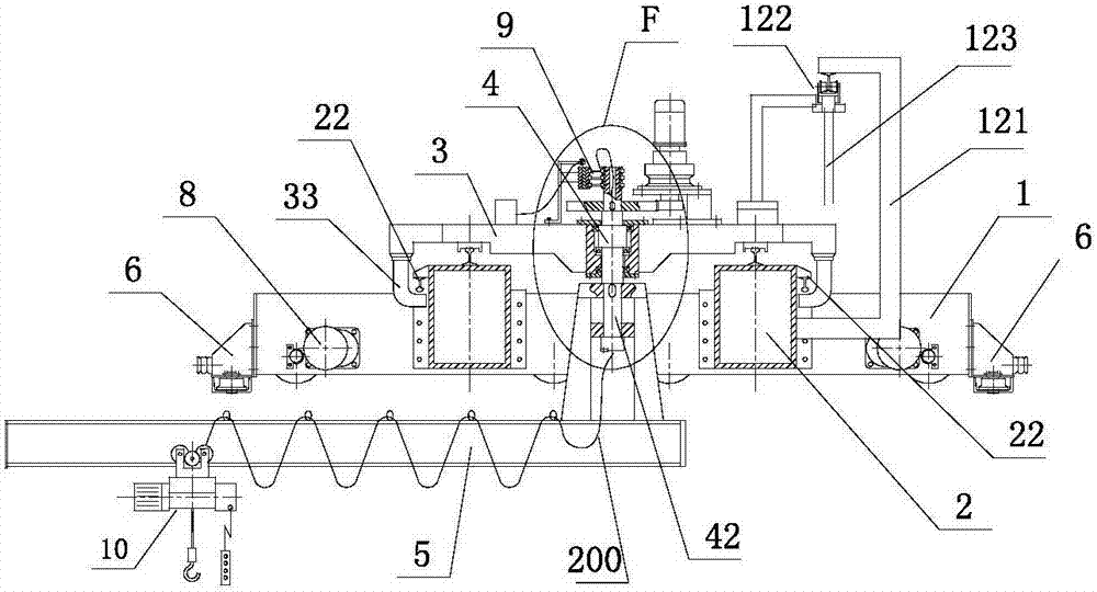
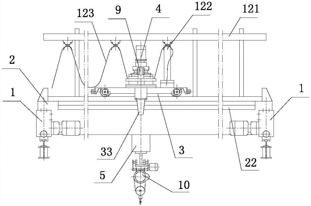
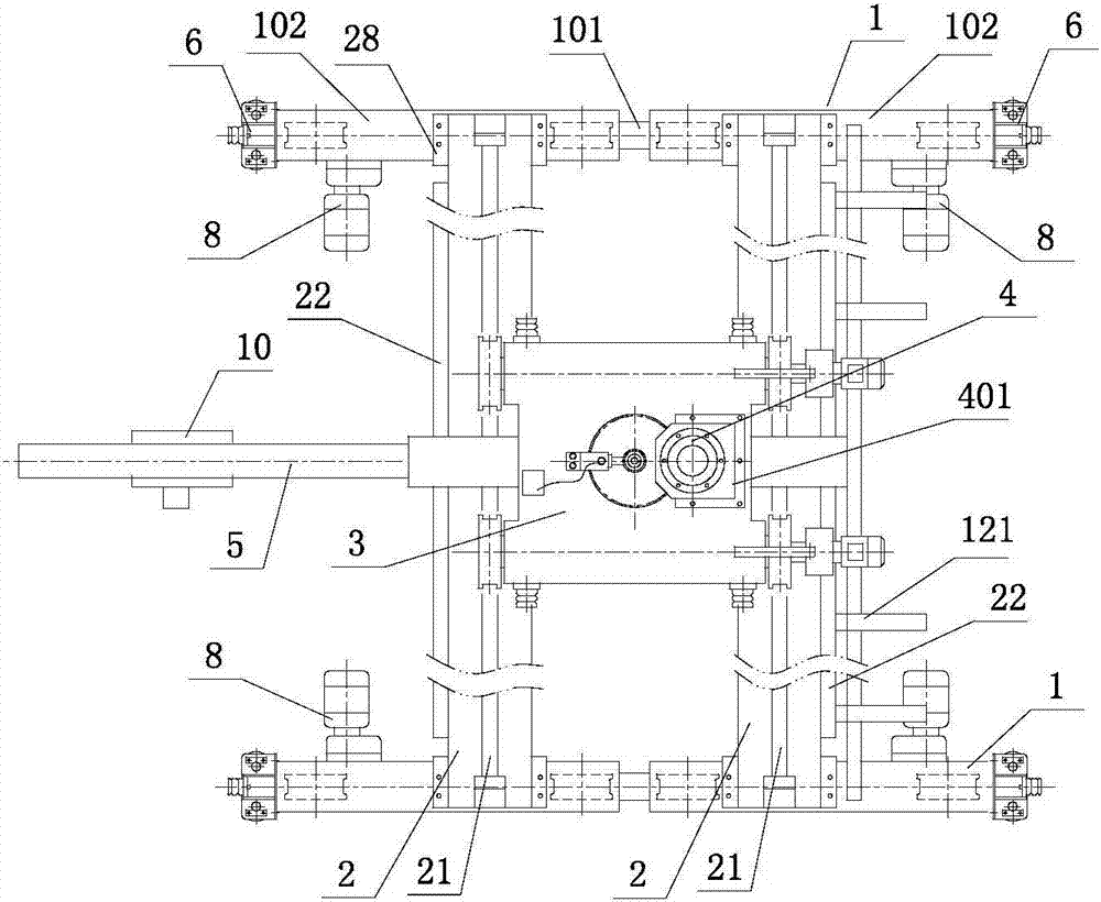
[0038] like figure 1 , figure 2 , image 3 , Figure 4 , Figure 5 As shown, a cantilever crane with a running trolley and a rotating mechanism with a collector slip ring includes two end beams 1 and two main beams 2; There is a movable hanging cable 123; a track 21 is arranged above the two main beams, and a running trolley 3 is connected to the track; the end beam 1 is composed of a balanced end beam 102 and a connecting rod 101; the end beam 1 is provided with a cart driving device 8 with an inner flange seat and an anti-tipping device 6; side rails 22 are provided on the outer side of the main girder; a safety hook 33 is connected to the lower part of the side rail, and the safety hook is connected to On the running trolley 3; the running trolley is provided with a rotating mechanism 4; the boom shaft 42 in the rotating mechanism is a hollow stepped shaft, and the middle part of the boom shaft is connected with the thrust bearing 45; the thrust bearing is connected to...


PUM


Abstract

This application discloses a cantilever crane with a running trolley and a rotating mechanism with a collector slip ring, including an end beam and a main beam; an electric pick-up frame and a hanging cable are arranged on the outside of one of the main beams; a rail is arranged above the main beam, and the track The running trolley is connected to the top; the end beam is composed of a balanced end beam and a connecting rod; a cart driving device and an anti-tipping device are installed on the end beam; side rails and safety hooks are set on the outer side of the main beam, and the safety hook is connected to a rotating The running trolley of the mechanism; the boom shaft in the rotating mechanism is connected with the thrust bearing and bearing A and bearing B; the thrust bearing is connected inside the bearing seat, and the bearing A and bearing B are respectively connected to the bearing seat through the fixed cover and the flange cover Both ends; the output shaft of the driving device is connected to the pinion gear, the pinion gear is meshed with the large gear, and the large gear is connected to the upper part of the boom shaft; the lower part of the boom shaft is connected to the cantilever member; the upper end of the boom shaft is connected to the collector slip ring; the cantilever The beam is connected to the electric hoist; the cantilever beam is under the main beam and can rotate at any angle.

Description

technical field [0001] The present application relates to the field of cranes, in particular to a cantilever crane with a running trolley, a rotating mechanism and a collector slip ring. Background technique [0002] Existing bridge cranes are used in enterprise workshops. Some workshops are equipped with many machine tools for processing and production. Products and raw materials need to be transported to the next workshop or other departments in real time; the hooks of the cranes in the workshop are hung from the trolley. For hoisting goods, the trolley can only run back and forth along the double girders of the crane, and the crane can only run back and forth along the cart rails on the cross columns on both sides of the workshop, so that the range of goods that the crane hook can lift is within the distance between the two cart rails in the workshop. Within the plane surrounded by the two ends, when the goods at the edge of the plane need to be hoisted, the hook will be ...

Claims


Application Information

Patent Timeline
Patent Type & Authority Applications(China)
IPC IPC(8): B66C17/04B66C11/10B66C9/14B66C9/08B66C9/16B66C23/84B66C13/12
CPCB66C17/04B66C9/08B66C9/14B66C9/16B66C11/10B66C13/12B66C23/84B66C2700/0342B66C2700/035B66C2700/084
Inventor 卢统华
Owner 卢统华
Why Eureka
Try Eureka