Crane with double trollies and balance weight cantilever beam

A technology of counterweights and cantilever beams, which is applied in the direction of traveling bridge cranes, cranes, and traveling mechanisms. The effect of the crane tipping over and being easy to install in place

Inactive Publication Date: 2018-07-10
福州市鼓楼区奇韵通自动化设备有限公司
View PDF0 Cites 0 Cited by
  • Summary
  • Abstract
  • Description
  • Claims
  • Application Information

AI Technical Summary

Problems solved by technology

[0002] Existing bridge cranes are used in enterprise workshops. Some workshops are equipped with many machine tools for processing and production. Products and raw materials need to be transported to the next workshop or other departments in real time; the hooks of the cranes in the workshop are hung from the trolley. For hoisting goods, the trolley can only run back and forth along the double girders of the crane, and the crane can only run back and forth along the cart rails on the cross columns on both sides of the workshop, so that the range of goods that the crane hook can lift is within the distance between the two cart rails in the workshop. Within the plane surrounded by the two ends, when the goods at the edge of the plane need to be hoisted, the hook will be pulled obliquely, and the items farther away from this plane (such as outside the workshop door, outside the span) cannot be hoisted. At this time, it can only be transferred with the help of other transportation equipment. Usually, the car drives into the workshop to lift the goods under the hook. Go to the hook to hand over the goods, and some set up a special cantilever crane at the workshop door (or workshop aisle) to transfer and dispatch the goods outside the workshop, first hoist the goods into the place where the crane hook of the workshop can reach , and then the cargo is hoisted by the crane to other stations in the workshop. The existing bridge crane used in this working condition cannot directly transfer the cargo with the workshop next door, and must use other transportation equipment to schedule operations, which brings considerable inconvenience. It also wastes manpower and material resources

Method used


Image

  • Crane with double trollies and balance weight cantilever beam
  • Crane with double trollies and balance weight cantilever beam
  • Crane with double trollies and balance weight cantilever beam

Examples


Embodiment approach

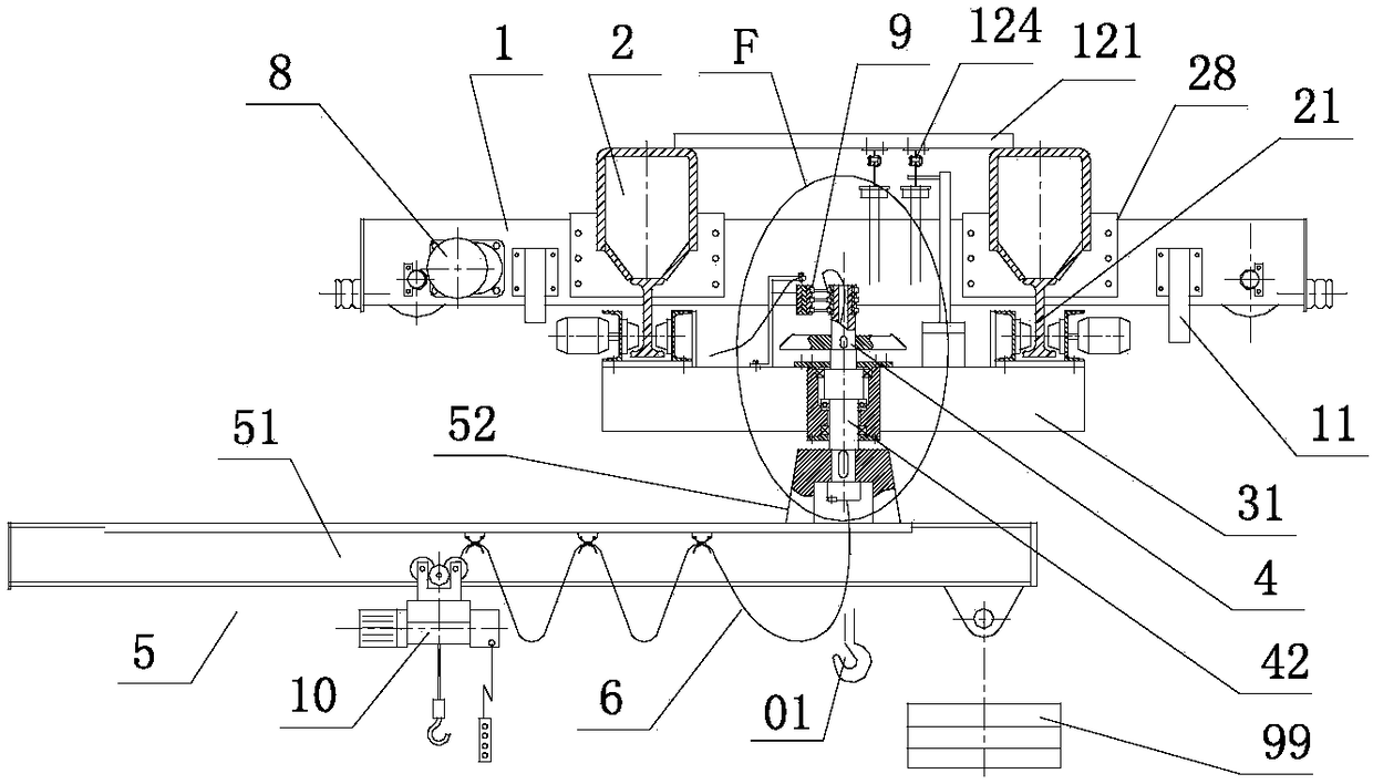
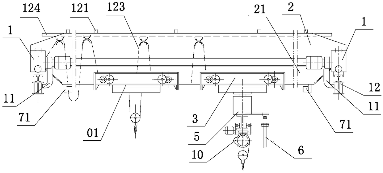
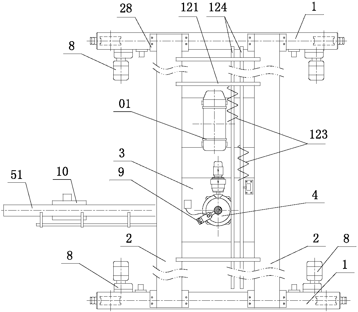
[0041] like figure 1 , figure 2 , image 3 As shown, a crane with double trolleys and counterweight cantilever beams includes a double-girder bridge frame 28; the double-girder bridge frame includes an end beam 1 and a main beam 2; a rail 21 is provided below the main beam; A hoisting trolley 01 is connected between the rails, and the hoisting trolley is provided with a hook-type hoisting and hoisting device; the two ends of the end beam 1 are provided with a cart driving device 8 with a splined sleeve wheel and an anti-tilting turn over device 11; a suspension end beam dolly 3 is also connected on the two described rails; the suspension end beam dolly is provided with a rotation mechanism 4; the lower end of the boom shaft 42 in the rotation mechanism is connected with the The suspension base 52 is connected, and the upper end is connected to the collector slip ring 9; the cantilever member 5 includes a cantilever beam 51 and a suspension base; the suspension base 52 is we...


PUM


Abstract

The invention discloses a crane with double trollies and a balance weight cantilever beam. A double-beam bridge frame comprises end beams and main beams. A lifting trolley is connected between rails below the two main beams. Large vehicle driving devices with spline sleeve wheels and anti-tipping devices are arranged at the two ends of the end beams respectively. A suspension end beam trolley is further connected to the rails. A rotating mechanism is arranged on the suspension end beam trolley. The lower end of a suspender shaft in the rotating mechanism is connected with a hanging base in a cantilever component, and the upper end of the suspender shaft is connected with a collecting slip ring. The cantilever component comprises the cantilever beam and the hanging base. The hanging base iswelded to one end of the cantilever beam. A balance weight is hung at the end, close to the hanging base, of the cantilever beam, the other end of the cantilever beam is connected with an electric hoist and can horizontally move along the cantilever beam, and the cantilever beam is located below the main beams, can stretch out of a workshop to work, and can rotate on the horizontal plane at any angle.

Description

technical field [0001] The present application relates to the field of cranes, in particular to a crane with double trolleys and counterweight cantilever beams. Background technique [0002] Existing bridge cranes are used in enterprise workshops. Some workshops are equipped with many machine tools for processing and production. Products and raw materials need to be transported to the next workshop or other departments in real time; the hooks of the cranes in the workshop are hung from the trolley. For hoisting goods, the trolley can only run back and forth along the double girders of the crane, and the crane can only run back and forth along the cart rails on the cross columns on both sides of the workshop, so that the range of goods that the crane hook can lift is within the distance between the two cart rails in the workshop. Within the plane surrounded by the two ends, when the goods at the edge of the plane need to be hoisted, the hook will be pulled obliquely, and the ...

Claims


Application Information

Patent Timeline
IPC IPC(8): B66C17/04B66C11/10B66C11/04B66C9/08B66C9/14B66C7/16B66C23/84B66C15/00
CPCB66C17/04B66C7/16B66C9/08B66C9/14B66C11/04B66C11/10B66C15/00B66C23/84
Inventor 卢统华
Owner 福州市鼓楼区奇韵通自动化设备有限公司
Why Eureka
Try Eureka